
Related Manuals for GESTRA NRG 10-52


Summary of Contents for GESTRA NRG 10-52
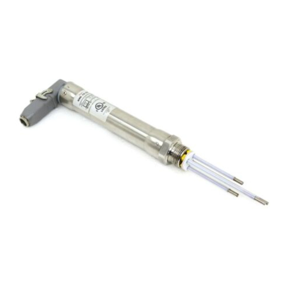
- Page 1 Level Electrode NRG 10-52 NRG 16-52 Original Installation Instructions 819123-02 E n g l i s h...
-
Page 2: Table Of Contents
Scope of supply ............................6 Name plate/marking ..........................6 Installation Tools ...............................7 Dimensions NRG 10-52, NRG 16-52 ......................8 NRG 10-52, NRG 16-52, step 1 .......................9 NRG 10-52, NRG 16-52, step 2 .......................9 Table “Functions” ............................9 Key .................................9 Examples of installation NRG NRG 10-52, NRG 16-52 .........................10... - Page 3 NRG 10-52, NRG 16-52 - connecting the five-pole connector ..............13 Connecting terminals in contact block ....................13 Commissioning, fault indication and troubleshooting ..............14 Removing and disposing of the level electrode Removing and disposing of level electrode NRG 10-52 / NRG 16-52 .............14...
-
Page 4: Important Notes
Usage for the intended purpose The level electrode NRG 10-52 / NRG 16-52 in conjunction with level switch NRS 1-.. is designed for signalling up to four different water levels and used for instance in steam boiler plants and (pressurized) hot-water installations or in condensate and feedwater tanks, e. -
Page 5: Directives And Standards
VdTÜV Bulletin “Wasserstand 100” (= Water Level 100) The level electrode NRG 10-52 / NRG 16-52 in conjunction with the following level switches is type ap- proved according to VdTÜV Bulletin “Wasserstand 100”: NRS 1-52, NRS 1-53, NRS 1-54 and NRS 1-55 or NRS 1-1, NRS 1-2, NRS 1-3 and NRS 1-5. -
Page 6: Technical Data
Technical data NRG 10-52, NRG 16-52 Operating pressure NRG 10-52: PN 6, 6 bar at 164 °C NRG 16-52: PN 40, 32 bar at 238 °C Mechanical connection Screwed G 1 A, ISO 228 Materials Screw-in body 1.4571, X6CrNiMoTi17-12-2 Electrode tips 1.4571, X6CrNiMoTi17-12-2 Insulation, spacer disks PTFE Five-pole connector 3.2161 G AlSi8Cu3... -
Page 7: Installation
Installation Note One level electrode NRG 10-52 / NRG 16-52 can be installed together with one GESTRA level electrode, one compact level switch or transmitter in a single protection tube or external level pot (inside diameter 100 m). Fig. 4 - 7. If the level limiting electrode is installed inside the vessel, it must be at least 40 mm away from the upper vent hole. -
Page 8: Dimensions Nrg 10-52, Nrg 16-52
Installation - continued - Dimensions NRG 10-52, NRG 16-52 ∅42 Screwed G 1 A, ISO 228 ∅ 40 G1, ISO 228-1 Fig. 2 Fig. 3 NRG 1..-52 with five-pole connector... -
Page 9: Nrg 10-52, Nrg 16-52, Step 1
Installation - continued - NRG 10-52, NRG 16-52, step 1 1. Determine required measuring lengths of electrode tips and enter data in table “Functions”. 2. Use a bolt cutter to cut the four electrode tips 1 2 3 4 2. Deburr faces of electrode tips. -
Page 10: Examples Of Installation
Examples of installation NRG 10-52, NRG 16-52 1" 1" DN 50 DN 50 ≤ 90° ≤ 90° ∅ 20 ∅ 20 Fig. 5 Fig. 4 Protection tube (provided on site) for Protection tube (provided on site) for installation inside the boiler installation inside the boiler 1"... -
Page 11: Key
Examples of installation - continued - Flange PN 40, DN 50, DIN EN 1092-01 (single electrode) Flange PN 40, DN 100, DIN EN 1092-01 (combination of electrodes) For the approval of the boiler standpipe with connecting flange the relevant regulations must be considered. - Page 12 Electrical connection NRG 10-52, NRG 16-52 with five-pole connector Fig. 9 Upper part of terminal box Level electrode NRG 10-52, NRG 16-52 Gasket Retaining bracket Ring Lower part of terminal box Cable gland Contact block Control cable Screw Sealing ring...
- Page 13 Connect the screen only once to the central earthing point (CEP) in the control cabinet. NRG 10-52, NRG 16-52 - connecting the five-pole connector 1. Swing up the retaining bracket j and detach the upper part of the terminal box o from the level electrode.
- Page 14 Before carrying out installation and maintenance work make sure that the equipment is cold. Removing and disposing of level electrode NRG 10-52 / NRG 16-52 1. Undo screw m. Fig. 9 2. Detach upper part of the terminal box o from the level electrode.
- Page 15 For your Notes...
- Page 16 Agencies all over the world: www.gestra.de GESTRA AG Münchener Straße 77 28215 Bremen Germany Telefon +49 421 3503-0 Telefax +49 421 3503-393 E-mail info@de.gestra.com www.gestra.de 819123-02/03-2017cm (808842-02) · GESTRA AG · Bremen · Printed in Germany...
Need help?
Do you have a question about the NRG 10-52 and is the answer not in the manual?
Questions and answers