
Related Manuals for GESTRA NRG 26-21


Summary of Contents for GESTRA NRG 26-21
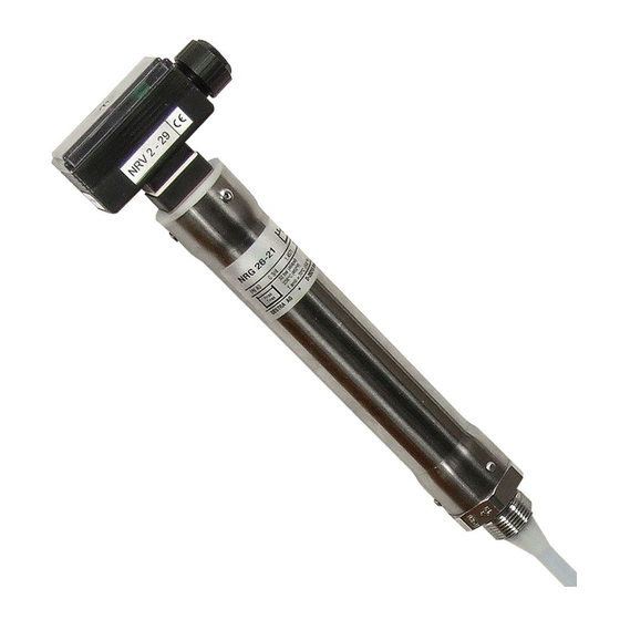
- Page 1 GESTRA Steam Systems NRG 26-21 English Installation & Operating Instructions 818774-05 Level Electrode NRG 26-21...
-
Page 2: Table Of Contents
Note on the Declaration of Conformity / Declaration by the Manufacturer ..........5 Technical data NRG 26-21 ..............................6 Scope of supply ............................7 Name plate/marking ..........................7 Installation Dimensions NRG 26-21 ...........................8 Key .................................8 NRG 26-21 ..............................9 Tools ...............................9 Examples of installation NRG 26-21 ............................10 NRG 26-21 ............................11... - Page 3 Factory setting ............................14 Establishing active measuring range (control range) ................14 Troubleshooting Indication, diagnosis and remedy ......................18 Maintenance Safety note ............................19 Cleaning the electrode rod ........................19 Removing and disposing of the level electrode Removing and disposing of level electrode NRG 26-21 ................19...
-
Page 4: Important Notes
Important notes Usage for the intended purpose The level electrode NRG 26-21 is used for continuous level monitoring in steam boilers and (pressu- rized) hot-water installations or in condensate and feedwater tanks. In conjunction with the level switch NRS 2-.. and the level controller NRR 2-.. the electrode can be used as water level controller with MIN/MAX alarm. -
Page 5: Directives And Standards
Directives and standards VdTÜV Bulletin "Wasserstand 100" (= Water Level 100) The level electrode NRG 26-21 in conjunction with the following level switches / controllers is type approved according to VdTÜV Bulletin "Wasserstand (= Water Level) 100": NRS 2-50, NRS 2-51, NRR 2-50, NRR 2-51, NRR 2-52 and NRR 2-53 or NRS 2-1, NRR 2-1, NRR 2-2 and NRT 2-1. -
Page 6: Technical Data
238°C Measuring range 1100 1200 1300 1400 1500 2000 Weight Approx. 1.8 kg (NRG 26-21 L=1000 mm) Electronic module NRV 2-29 Supply voltage 12 V DC Response sensitivity Water ≥ 0.5 µS/cm Range 1: Water ≥ 20 µS/cm Range 2: Fuel oil EL ε... -
Page 7: Scope Of Supply
UL 508 and CSA C22.2 No. 14-13, Standards for Industrial Control Equipment. File E243189. Scope of supply NRG 26-21 1 Level electrode NRG 26-21 1 Joint ring 27 x 32, form D, DIN 7603, 2.4068, bright annealed 1 Installation manual Name plate/marking... -
Page 8: Installation
Installation Dimensions NRG 26-21 ∅42 G¾ A, ISO 228 ∅ 33 G¾ A, ISO 228 ∅ 15 Ra 3.2 Fig. 3 Fig. 2 NRG 26-21 Thermal insulation, provided on site, Electrode thread d = 20 mm (outside of thermal insulation of... -
Page 9: Nrg 26-21
Installation - continued - Note One level electrode NRG 26-21 can be installed together with one GESTRA level elec- trode, one level switch or transmitter in a single protection tube or an external level pot (inside diameter DN80/DN100). Fig. 4 - 7. If the level limiting electrode is installed inside the vessel, it must be at least 40 mm away from the upper vent hole. -
Page 10: Examples Of Installation
Examples of installation NRG 26-21 G ¾ G ¾ DN 50 DN 50 ≤ 90° ≤ 90° ∅ 20 ∅ 20 Fig. 5 Fig. 4 Protection tube (provided on site) for Protection tube (provided on site) for installation inside the boiler installation inside the boiler G ¾... -
Page 11: Nrg 26-21
Examples of installation - continued - NRG 26-21 - continued - Tube, e. g. 33.7 x 3.2 Fig. 8 Inclined installation e. g. in steam boilers Flange PN 40, DN 50, DIN EN 1092-01 (single electrode) Flange PN 40, DN 100, DIN EN 1092-01 (combination of electrodes) For the approval of the boiler standpipe with connecting flange the relevant regulations must be considered. -
Page 12: Electrical Connection
Electrical connection NRV 2-29 ≥ 0 V ≤ 7 V DC 12 V DC Measuring voltage Supply voltage for NRV 2-29 1 M 3 Fig. 9 Fig. 9 Electronic module NRV 2-29 integrated in terminal box Screw M4 Sealing plate Cover Terminal box (electronic module NRV 2-29) Seal... -
Page 13: Connection Of Level Electrode
12 13 14 15 Fig. 10 Fig. 11 +12V +12V NRG 26-21 NRG 26-21 Attention Please observe the instructions given in the installation & operating manual for the level switches / controllers NRS 2-50, NRS 2-51, NRR 2-50, NRR 2-51, NRR 2-52 and... -
Page 14: Basic Settings
Basic settings Factory setting The code switch r is set at our factory so that the max. measuring range for water (conductivity ≥ 20 μS/cm) is activated. The max. measuring range is the range between the lower and the upper end of the measuring range. - Page 15 Basic settings - continued - Establishing active measuring range (control range) - continued - Ascertain the type of fluid that will be measured. Determine the active measuring range (control range) in mm. Refer to diagrams u, v or v for the required code switch settings for water and fuel oil EL. Example: Max.
- Page 16 Basic settings - continued - Establishing active measuring range (control range) - continued - Diagram for water, conductivity ≥ 0.5 μS/cm Code switch 4+5 ON 4 ON 3 ON 2 ON 1000 1200 1400 1600 1800 2000 Selected (active) measuring range [mm] Fig.
- Page 17 Commissioning procedure Applying supply voltage Please check that the level electrode is wired in accordance with the wiring diagram (Fig. 10, 11) and switch on supply voltage of the connected level switch / controller. Checking measuring range Before commissioning the level electrode make sure that the active measuring range (= control range) agrees with the service conditions of your installation.
-
Page 18: Troubleshooting
Troubleshooting Indication, diagnosis and remedy Attention Before carrying out the fault diagnosis please check: Supply voltage: Is the level electrode supplied with the voltage specified on the name plate? Wiring: Is the wiring in accordance with the wiring diagram? Malfunctions Equipment does not work accurately Error Remedy... -
Page 19: Maintenance
Before cleaning the electrode rod decommission and remove the level electrode. Clean the electrode rod with a wet cloth. Removing and disposing of the level electrode Removing and disposing of level electrode NRG 26-21 1. Switch off supply voltage. 2. Unscrew screw e and remove cover =. - Page 20 Agencies all over the world: www.gestra.com GESTRA AG Münchener Straße 77 28215 Bremen Germany Telefon +49 421 3503-0 Telefax +49 421 3503-393 E-mail info@de.gestra.com www.gestra.de 818774-05/07-2017cm (808388-11)· GESTRA AG · Bremen · Printed in Germany...
Need help?
Do you have a question about the NRG 26-21 and is the answer not in the manual?
Questions and answers