GESTRA LRG 16-4 Installation & Operating Manual
Conductivity electrode
Hide thumbs
Also See for LRG 16-4:
- Installation instructions manual (16 pages) ,
- Installation instructions manual (8 pages) ,
- Installation & operating manual (72 pages)

Related Manuals for GESTRA LRG 16-4


Summary of Contents for GESTRA LRG 16-4
- Page 1 Conductivity Electrode LRG 16-4 Original Installation & EN (USA) Operating Manual 850700-00 English...
-
Page 2: Table Of Contents
Connecting a conductivity electrode ....................20 Bringing into service .......................... 20 Assigning the four-pole connector of the LRG 16-4 ................ 20 Fault indications and troubleshooting ....................21 Indications, diagnosis and corrective action ................... 21 LRG 16-4 - USA - Installation & Operating Manual - 850700-00... - Page 3 Contents Maintenance ............................22 Cleaning the measuring electrode ....................22 Taking out of service .......................... 23 Disposal .............................. 24 Returning decontaminated equipment ....................24 UL components ........................... 24 LRG 16-4 - USA - Installation & Operating Manual - 850700-00...
-
Page 4: Content Of This Manual
All rights reserved. Any misuse, particularly reproduction and dissemination to third parties, is not permitted. The General Terms & Conditions of GESTRA AG apply. Scope of supply, product package LRG 16-4 1 conductivity electrode LRG 16-4 1 Installation & Operating Manual LRG 16-4 - USA - Installation & Operating Manual - 850700-00... -
Page 5: How To Use This Manual
How to use this Manual This Installation & Operating Manual describes the correct use of the LRG 16-4 conductivity electrode. It applies to persons who integrate this equipment in control systems, install, bring into service, operate, maintain and dispose of this equipment. Anyone carrying out the above- mentioned activities must have read this Installation &... -
Page 6: Types Of Warning
Warning of a dangerous situation that may possibly result in death or serious injury. CAUTION Warning of a situation that may result in minor or moderate injury. ATTENTION Warning of a situation that results in damage to property or the environment. LRG 16-4 - USA - Installation & Operating Manual - 850700-00... -
Page 7: Specialist Terms, Abbreviations
A boiler that is operated at 145 psi (10 bar) and 356 °F (180 °C) may be designed to withstand a pressure of 870 psi (60 bar) and a temperature of 527 °F (275 °C), for example, which is therefore not necessarily its operating point. LRG 16-4 - USA - Installation & Operating Manual - 850700-00... -
Page 8: Usage For The Intended Purpose
Usage for the intended purpose The LRG 16-4 conductivity electrode may only be used in conjunction with LRS 1-.. conductivity switches or LRR 1-.. conductivity controllers for measuring conductivity in liquid conductive media. The LRG 16-4 conductivity electrode can be used as a conductivity limiter or blowdown controller... -
Page 9: Basic Safety Information
Check that the plant is not carrying live voltage before commencing work. ■ Danger to life! Hot steam or hot water can suddenly escape from a faulty LRG 16-4 conductivity electrode. Shocks and impacts during transport or installation can result in damage to or leaks in the conductivity electrode, causing pressurized hot steam or hot water to escape through the pressure relief hole. -
Page 10: Required Personnel Qualifications
Persons trained by the plant operator to work Refits Specialist staff with pressure and temperature. Notes on product liability The manufacturer cannot accept any liability for damages resulting from improper use of the equipment. LRG 16-4 - USA - Installation & Operating Manual - 850700-00... -
Page 11: Function
Function The LRG 16-4 conductivity electrode is used as a conductivity limiter and blowdown controller in steam boilers in combination with the following equipment: Conductivity switch LRS 1-50 Conductivity controller LRR 1-50 Conductivity controller LRR 1-52 In addition, this equipment can monitor conductivity in condensate and feedwater circuits and in cooling and cleaning water. -
Page 12: Technical Data
Ambient temperature: 32-158°F (0-70°C) Environmental rating: NEMA 1 Wiring: Use Copper Conductors Only, OPERATING CONTROL use 60/75°C Conductors E513189 Use with accessory: LRS 1-50, LRR 1-50, LRR 1-52 Fig. 1 LRG 16-4 - USA - Installation & Operating Manual - 850700-00... -
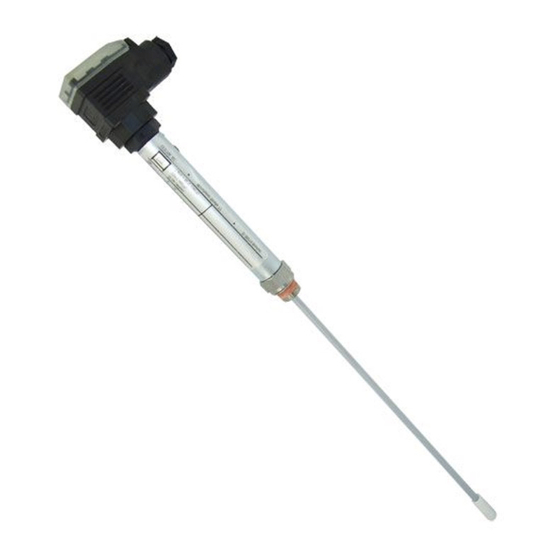
Page 13: Overall View
Overall view Fig. 2 Four-pole connector Electrode thread Cable lead-through Measuring electrode Cover tube Enlarged measuring surface LRG 16-4 - USA - Installation & Operating Manual - 850700-00... -
Page 14: Dimensions
15.75 in (400 mm) ■ 19.69 in (500 mm) ■ 23.62 in (600 mm) ■ 31.50 in (800 mm) ■ 39.37 in (1000 mm) ■ 47.24 in (1200 mm) ■ LRG 16-4 - USA - Installation & Operating Manual - 850700-00... -
Page 15: Preparing For Installation
Preparing for installation You will need the following tools: Open-ended wrench size 22 ■ LRG 16-4 - USA - Installation & Operating Manual - 850700-00... -
Page 16: Installation
(LW), see installation example in Fig. 5 Installation examples can be found on page 18. ■ LRG 16-4 - USA - Installation & Operating Manual - 850700-00... -
Page 17: Installing The Lrg 16-4
(The band grounding clamp is available as an optional accessory) Next, measure the resistance again. The value must be < 10 ohms and entered as followed: Measured resistance: __________________________ ohms Boiler wall Visible thread Fig. 4 LRG 16-4 - USA - Installation & Operating Manual - 850700-00... -
Page 18: Installation Examples With Dimensions
For conductivity monitoring and continuous boiler blowdown, the conductivity electrode is installed in the blowdown line via a separate level pot LRG 16-4 Fig. 6 Shut-off valve GAV Continuous blowdown valve BAE Boiler drum Level pot Level pot LRG 16-4 - USA - Installation & Operating Manual - 850700-00... -
Page 19: Electrical Connection
Cable gland M 16 (PG 9) Upper part of connector Terminal assignment Connection plate Insulating plate Measuring electrode Tools Screwdriver 3/32 in (2.4 mm) ■ Screwdriver 1/8 in (3.2 mm), fully insulated ■ LRG 16-4 - USA - Installation & Operating Manual - 850700-00... -
Page 20: Connecting A Conductivity Electrode
Route the connecting cable between items of equipment separately from power ■ lines. Check the connection of the shield to the central grounding point (CGP) in the ■ control cabinet. LRG 16-4 - USA - Installation & Operating Manual - 850700-00... -
Page 21: Fault Indications And Troubleshooting
Replace equipment if necessary. Attention Please pay attention to the LRS 1-50, LRR 1-50 and LRR 1-52 ■ Installation & Operating Manuals for bringing into service and further troubleshooting. LRG 16-4 - USA - Installation & Operating Manual - 850700-00... -
Page 22: Maintenance
Wipe off loose deposits with a fat-free cloth. ■ Scrub off stubborn deposits using sandpaper (medium grain). ■ Re-install the conductivity electrode. Pay attention to the information in the ‘Installation’ and ‘Electrical connection’ sections. LRG 16-4 - USA - Installation & Operating Manual - 850700-00... -
Page 23: Taking Out Of Service
1. Undo the screw a. Fig. 7 2. Detach the upper part c of the connector from the conductivity electrode. 3. Make sure the equipment is not hot or under pressure before dismantling it. LRG 16-4 - USA - Installation & Operating Manual - 850700-00... -
Page 24: Disposal
The term ‘media’ can refer to solid, liquid or gaseous substances or mixtures, as well as radiation. GESTRA AG can accept returned products only if accompanied by a completed and signed return note and also a completed and signed declaration of decontamination. - Page 25 For your notes LRG 16-4 - USA - Installation & Operating Manual - 850700-00...
- Page 26 For your notes LRG 16-4 - USA - Installation & Operating Manual - 850700-00...
- Page 27 For your notes LRG 16-4 - USA - Installation & Operating Manual - 850700-00...
- Page 28 You can find our authorized agents around the world at: www.gestra.com GESTRA AG Münchener Straße 77 28215 Bremen Germany Tel. +49 421 3503 0 +49 421 3503 393 e-mail info@de.gestra.com www.gestra.com 850700-00/08-2021cm (809150-00) · GESTRA AG · Bremen...
Need help?
Do you have a question about the LRG 16-4 and is the answer not in the manual?
Questions and answers