Sign In
Upload
Download
Table of Contents
Contents
Add to my manuals
Delete from my manuals
Share
URL of this page:
HTML Link:
Bookmark this page
Add
Manual will be automatically added to "My Manuals"
Print this page
×
Bookmark added
×
Added to my manuals
Manuals
Brands
GESTRA Manuals
Measuring Instruments
VK 14
Original installation instructions
GESTRA VK 14 Original Installation Instructions
Vaposcope sight glasses
Hide thumbs
1
Table Of Contents
2
3
4
5
6
7
8
9
10
11
12
13
14
15
16
17
18
19
20
21
22
23
24
25
26
27
28
page
of
28
Go
/
28
Contents
Table of Contents
Troubleshooting
Bookmarks
Table of Contents
Table of Contents
Foreword
Availability
Formatting Features in the Document
Safety
Use for the Intended Purpose
Basic Safety Notes
Information on Property Damage or Malfunctions
Qualification of Personnel
Protective Gear
Typographic Features of Warning Notes
Formatting Features for Warnings of Property Damage
Description
Scope of Supply and Equipment Specification
Task and Function
Storing and Transporting the Equipment
Storing the Equipment
Transporting the Equipment
Mounting and Connecting the Equipment
Preparing Installation
Connecting the Equipment
Operation
After Operation
Maintaining the Equipment
Removing External Dirt Deposits
Servicing the Equipment and Installing Spare Parts
Troubleshooting
Putting the Equipment out of Operation
Removing Harmful Substances
Removing the Equipment
Re-Using Equipment after Storage
Returning the Equipment
Disposing of the Equipment
Technical Data
Dimensions and Weights
Pressure & Temperature Ratings
Declaration of Conformity - Standards and Directives
Advertisement
Quick Links
Download this manual
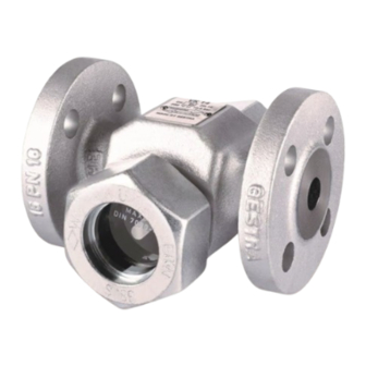
Vaposcope Sight Glasses
®
VK 14
VK 16
Original Installation Instructions
818577-03
Table of
Contents
Previous
Page
Next
Page
1
2
3
4
5
Advertisement
Table of Contents
Need help?
Do you have a question about the VK 14 and is the answer not in the manual?
Ask a question
Questions and answers
Related Manuals for GESTRA VK 14
Measuring Instruments GESTRA VK 16 Original Installation Instructions
Vaposcope sight glasses (28 pages)
Measuring Instruments Gestra LRGT 16-1 Installation & Operating Instructions Manual
Conductivity transmitter lrgt 16-1; conductivity transmitter lrgt 16-2; conductivity transmitter lrgt 17-1 (28 pages)
Measuring Instruments Gestra NRG 26-21 Installation & Operating Instructions Manual
Steam systems level electrode (20 pages)
Measuring Instruments GESTRA LRG 16-40 Original Installation Instructions
Conductivity electrode (32 pages)
Measuring Instruments GESTRA NRT 2-1 Installation And Service Instructions Manual
Level transmitter (8 pages)
Measuring Instruments GESTRA NRG 16-51 Original Installation & Operating Manual
Level electrodes (32 pages)
Measuring Instruments GESTRA NRG 26-40 Original Installation Instructions
Level electrode (28 pages)
Measuring Instruments GESTRA LRG 16-60 Installation & Operating Manual
Conductivity electrodes (72 pages)
Measuring Instruments GESTRA NRG 211-1 Original Installation Instructions
Level electrode (20 pages)
Measuring Instruments GESTRA NRS 1-50 Instruction Manual
Water level limiter level switch (2 pages)
Measuring Instruments GESTRA NRG 16-61 Installation & Operating Manual
Level electrodes (60 pages)
Measuring Instruments GESTRA LRG 16-4 Installation & Operating Manual
Conductivity electrode (28 pages)
Measuring Instruments GESTRA NRG 16-38 S Original Installation Instructions
Level electrode (48 pages)
Measuring Instruments GESTRA NRG 16-38S Original Installation Manual
Water level limiter with level electrode (44 pages)
Measuring Instruments GESTRA NRG 10-52 Original Installation Instructions
(16 pages)
This manual is also suitable for:
Vk 16
Table of Contents
Print
Rename the bookmark
Delete bookmark?
Delete from my manuals?
Login
Sign In
OR
Sign in with Facebook
Sign in with Google
Upload manual
Upload from disk
Upload from URL


Need help?
Do you have a question about the VK 14 and is the answer not in the manual?
Questions and answers