
Related Manuals for GESTRA NRG 17-51


Summarization of Contents
How to Use This Manual
Availability of Installation & Operating Manual
Information on keeping the manual accessible for operators and third parties.
Illustrations and Symbols Used
Keys to Illustrations
Explains symbols like 'i' for additional information and reading the manual.
Hazard Symbols in This Manual
Danger Zone, Dangerous Situation
Defines the hazard symbol indicating a dangerous situation.
Types of Warning
DANGER
Warning of a dangerous situation resulting in death or serious injury.
WARNING
Warning of a dangerous situation possibly resulting in death or serious injury.
CAUTION
Warning of a situation resulting in minor or moderate injury.
ATTENTION
Warning of a situation resulting in damage to property or the environment.
Specialist Terms and Abbreviations
GESTRA AG Equipment Designations
Lists equipment and type designations used by GESTRA AG.
SELV Definition
Definition of Safety Extra Low Voltage.
Operating Point of the Plant
Describes operating parameters within a plant's nominal range.
Usage and Compliance
Intended Purpose of NRG Electrodes
Describes use with NRS 1-51 for high-level alarm in steam/hot water boilers.
Applicable Standards
Lists relevant UL and CSA standards for electrical controls and level sensing.
Admissible System Components
States NRG 1...-51 can be operated with NRS 1-51 as a protective control.
Warning Against Improper Use
Warns against use in explosive atmospheres and requires specific rating plates.
Basic Safety Information
Scalding Hazard Warning
Warns against removing electrode under pressure; only at 0 psi.
Burn Hazard Warning
Advises allowing electrode to cool before performing work.
Electric Shock Hazard
Reminds to switch off voltage before performing electrical work.
Steam/Water Escape Hazard
Warns of potential escape from faulty electrodes; avoid shocks.
Repair and Replacement Policy
States only manufacturer can repair; use identical replacement parts.
Personnel Qualifications and Liability
Personnel Qualifications by Activity
Specifies required staff qualifications for integration, installation, operation, and maintenance.
Product Liability Disclaimer
Manufacturer not liable for damages resulting from improper use of equipment.
Functionality and Safety Guidelines
Level Electrode Functionality
Explains conductivity measurement and self-monitoring features.
Protective Tube and Level Pot Requirements
Details need for protective tubes and pipe sizes for level pots.
Safety Information for Installation
Emphasizes qualified personnel and checking rating plates before operation.
Technical Data
Service Pressure Specifications
Lists service pressure for NRG 16-51, 17-51, 19-51 at specified temperatures.
Mechanical Connection Details
Specifies the thread type as 1" - 11.5 NPT.
Materials Used
Lists materials for electrode body, extension, insulation, and connectors.
Available Lengths
Details the standard lengths supplied for the electrode extension.
Electrical Connection Types
Describes connection types: four-pole connector and terminal box.
Protection Ratings (IP/NEMA)
Specifies IP 65 and NEMA type ratings for different models.
Admissible Ambient Temperature
Maximum permissible ambient temperature for operation.
Weight Information
Provides weight for models with and without extensions.
Other Technical Information
Includes operating control type, pollution degree, and impulse voltage.
Rating Plate and Identification
Equipment Designation and Pressure Rating
Identifies model name and pressure limits shown on the rating plate.
Safety and Manufacturer Details on Plate
Includes instructions to read manual and manufacturer information.
Thread, Material, and Protection Specs
Details thread type, material, and protection specifications.
Pressure and Temperature Limits
Shows maximum pressure and temperature limits indicated on the plate.
CE Marking and Type Approval
Notes the presence of CE marking and type approval numbers.
Disposal Information Symbol
Indicates the symbol for disposal information.
UL Components and Operating Control
Shows UL registration and operating control details.
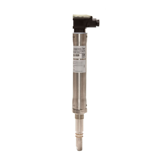
Overall View of NRG 16-51, NRG 17-51, NRG 19-51
Key to Components
Identifies parts: terminal box, cable entry, cover tube, electrode thread, measuring electrode.
Dimensions for NRG 16-51, NRG 17-51, NRG 19-51 (Four-Pole Connector)
Dimensions for NRG 16-51 and NRG 17-51
Provides overall dimensions for NRG 16-51 and 17-51 models with four-pole connector.
Dimensions for NRG 19-51
Provides overall dimensions for the NRG 19-51 model with four-pole connector.
Overall View of NRG 16-51F, NRG 17-51F, NRG 19-51F
Key to Components
Identifies parts: terminal box, cable entry, cover tube, electrode thread, measuring electrode.
Dimensions for NRG 16-51F, NRG 17-51F, NRG 19-51F (Aluminum Terminal Box)
Dimensions for NRG 16-51F and NRG 17-51F
Provides overall dimensions for NRG 16-51F and 17-51F models with terminal box.
Dimensions for NRG 19-51F
Provides overall dimensions for the NRG 19-51F model with terminal box.
Preparing for Installation
Outdoor Installation Considerations
Advises on environmental influences and protection measures for outdoor installations.
Required Tools for Installation
Lists necessary tools for the installation process.
Installation Procedure
Danger Warning: Hot Steam/Water Escape
Warns of scalding risk when unscrewing under pressure.
Warning: Hot Level Electrode
Warns of burn risk from hot electrode; ensure cooling before handling.
Attention: Incorrect Installation Risks
Notes potential malfunctions from bending electrodes or improper installation.
General Installation Notes
Includes notes on protective tubes, spacing, incline limits, and outdoor model types.
Installing NRG 16-51, NRG 17-51, NRG 19-51 (Step 1)
Assembly of Electrode Extension
Details screwing the extension, marking, cutting, and fitting washer/retaining ring.
Installing NRG 16-51, NRG 17-51, NRG 19-51 (Step 2)
Thread Preparation and Tightening
Advises on PTFE tape usage, wrench selection, and ensuring visible thread.
Electrical Contact Verification
Instructs to measure resistance (< 10 ohms) between electrode and boiler wall.
Installation of NRG 16-51F, NRG 17-51F, NRG 19-51F with Terminal Box
Terminal Box Rotation and Connection
Details rotating the terminal box, tightening nuts, and fitting the cover.
Installation Examples: Protective Tubes
Fig. 17 Protective Tube (Internal Water Level Limiter)
Shows dimensions for a protective tube used as an internal water level limiter.
Fig. 18 Protective Tube (Internal Limiter with Control)
Shows dimensions for a protective tube for internal limiter with level control.
Installation Examples: Level Pots
Fig. 19 Level Pot (External High-Level Alarm)
Shows dimensions for a level pot used as an external high-level alarm.
Electrical Connection - Four-Pole Connector Diagram
Key to Four-Pole Connector Components
Identifies parts of the four-pole connector assembly.
Electrical Connection - Procedures and Tools
Connecting the Level Electrode
Instructions for connecting using specific cables and wiring to NRS 1-51.
Connecting Four-Pole Connector Models
Step-by-step guide for connecting NRG 16-51, 17-51, 19-51 with four-pole connector.
Connecting Aluminum Terminal Box Models
Steps for connecting NRG 16-51F, 17-51F, 19-51F with aluminum terminal box.
Tools for Electrical Connection
Lists tools required for performing electrical connections.
Electrical Connection - Wiring Diagrams
Main Wiring Diagram
Shows wiring diagrams for NRG 1...-51 and NRG 1...-51F models.
Four-Pole Connector Wiring
Illustrates the electrical connection for four-pole connector models.
Aluminum Terminal Box Wiring
Illustrates the electrical connection for aluminum terminal box models.
Service and Removal Procedures
Bringing into Service and Troubleshooting
Refers to NRS 1-51 manual for bringing into service and troubleshooting.
Taking Out of Service - Safety Warnings
Safety warnings regarding scalding and burns during removal.
Procedure for Removing NRG 1..-51 Electrode
Specific steps for safely removing the standard NRG 1..-51 model.
Procedure for Removing NRG 1..-51F Electrode
Specific steps for safely removing the NRG 1..-51F model.
Disposal and Equipment Returns
Disposal Guidelines
Mentions following statutory waste disposal provisions.
Handling Hazardous Media for Returns
Requires draining and decontamination for products exposed to hazardous media.
Equipment Return Procedure
Outlines steps for returning equipment, including return note and declaration.
UL Component Registration
States NRG 1...-51 level electrode is registered under XACN.E513189.
Need help?
Do you have a question about the NRG 17-51 and is the answer not in the manual?
Questions and answers