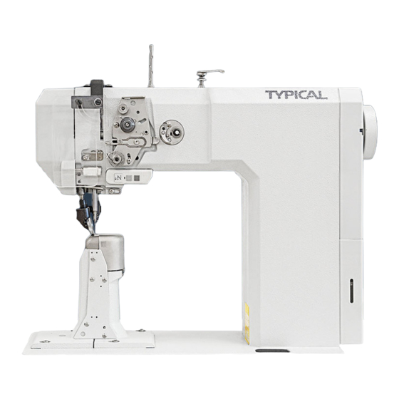
Table of Contents
Advertisement
Advertisement
Table of Contents

Summarization of Contents
Safety Guidelines
Safety Directives
Compliance with European regulations and general statutory requirements.
General Safety Notes for Operators
Instructions for safe operation, maintenance, and handling of the machine.
Understanding Safety Symbols
Explanation of danger and caution symbols used in the manual.
Important Points for the User
Key responsibilities and requirements for machine users.
Personnel Responsibilities and Safety
Duties of operating and specialist personnel regarding machine safety.
Specific Danger Warnings
Warnings about specific hazards like needle injury, tipping, and crushing.
Technical Specifications
TYPICAL 571, 574, 591 Model Details
Detailed specifications for stitch type, dimensions, speed, and connectivity.
Needles and Threads
Recommended needle systems and thread types for different models.
Model and Subclass Information
Overview of possible machine models and their subclasses for various materials.
Transportation, Packing, and Storage
Transportation to Customer's Premises
Information regarding the delivery and packing of the machines.
Transportation Within Customer Premises
Guidelines for safe movement of the machine at the user's location.
Disposal of Packing Materials
Customer responsibility for disposing of machine packing materials.
Machine Storage Recommendations
Instructions for storing the machine when not in use.
Machine Controls
On/Off Switch Operation
Controls the main power supply to the machine.
Machine Head Control Keys
Functions of keys on the machine head for reverse sewing and parameter access.
Bobbin Thread Monitoring
Operation of the stitch counting and bobbin thread monitoring system.
Pedal Functions
Defines pedal positions for sewing, presser lifting, and thread trimming.
Roller Presser Lifting Lever
Mechanism for manually raising the roller presser.
Knee Lever Operation
Control for raising the roller presser using knee action.
Stitch Length Setting Key
Key used with the balance wheel to set stitch length.
Swing-Out Roller Presser
Procedure to swing out the roller presser for access.
Edge Trimmer for Model 571
Operation and maintenance of the edge trimmer for model 571.
Edge Trimmer for Models 574/591
Operation and maintenance of the edge trimmer for models 574 and 591.
Control Panel
Reference to separate manual for control panel functions.
Installation and Commissioning
General Installation Requirements
Ensuring proper mounting, commissioning by qualified personnel, and safety regulations.
Adjusting Table-Top Height
Steps to adjust the height of the machine's table top.
Fitting the Tilt Lock Mechanism
Installation of the tilt lock for machine head safety.
Fitting the Machine Cover
Procedure for attaching the machine's cover panels.
Mounting the Flange Motor
Instructions for attaching the flange motor assembly.
Mounting Toothed Belt and Tension
Fitting and tensioning the drive belt for the motor.
Mounting the Belt Guard
Attaching the protective guard for the motor's belt drive.
Connecting Power and Earth Cables
Wiring guide for connecting electrical components and grounding.
Connecting the Safety Switch
Installation of the safety switch for machine head positioning.
Checking Start Inhibitor Function
Verification of the safety interlock for tilted machine heads.
Fitting the Reel Stand
Procedure for assembling and installing the thread stand.
Commissioning the Machine
Final checks and setup before initial machine operation.
Switching the Machine On and Off
Reference to the Controls section for power operations.
Machine Drive Unit Basic Position
Setting the fundamental operational state of the drive unit.
Drive Unit Setup for P40 ED
Parameter settings for P40 ED drive unit setup.
Drive Unit Setup for P44 PD-L
Parameter settings for P44 PD-L drive unit setup.
Setting Up the Sewing Machine
General Setup Precautions
Mandatory observance of instructions and safety regulations during setup.
Inserting the Needle Correctly
Correct procedure for inserting the machine needle.
Winding Bobbin Thread and Tension
Guide to winding bobbins and setting thread tension.
Bobbin Case Removal and Insertion
Steps for safely handling the bobbin case.
Threading Bobbin Case and Tension
Threading the bobbin case and adjusting its tension.
Needle Threading for Models 571/591
Needle threading and tension adjustment for models 571 and 591.
Needle Threading for Model 574
Needle threading and tension adjustment for model 574.
Setting the Stitch Length
Procedure for setting the desired stitch length.
Adjusting the Stitch Counter
Adjusting the stitch counter for bobbin thread monitoring.
Care and Maintenance
Servicing and Maintenance Intervals
Schedule for routine maintenance tasks.
Daily Cleaning Procedures
Instructions for daily cleaning of machine parts.
Oiling the Hook
Procedure for lubricating the hook mechanism.
Hook Lubrication Oil Level
Checking and maintaining the oil level for hook lubrication.
Lubricating the Bevel Gears
Annual greasing procedure for the machine's bevel gears.
Filling Thread Lubrication Reservoir
Procedure for refilling the thread lubrication system's oil reservoir.
Parameter Settings Overview
General information on accessing and modifying machine parameters.
Detailed Parameter List
Detailed list of machine parameters and their values.
Mounting the Table Top
Tilted Work Base Dimensions
Dimensions and specifications for the tilted work base.
Table Top Cutout Dimensions
Specifications for cutting out the table top for machine installation.
Table Top Mounting for P40 ED
Instructions for mounting the table top with P40 ED control.
Table Top Mounting for P44 PD-L
Instructions for mounting the table top with P44 PD-L control.
Circuit Diagrams and Block Diagrams
Circuit Diagram Reference List
List referencing circuit diagrams for P40 ED and P44 PD-L control packages.
Block Diagram for P40 ED Control Unit
Schematic overview of the TYPICAL 570/590 with P40 ED control unit.
Circuit Diagrams for P40 ED Control Unit
Detailed electrical circuit diagrams for the P40 ED control package.
Circuit Diagrams for P44 PD-L Control Unit
Detailed electrical circuit diagrams for the P44 PD-L control package.


Need help?
Do you have a question about the TW1-591 and is the answer not in the manual?
Questions and answers