Table of Contents
Advertisement
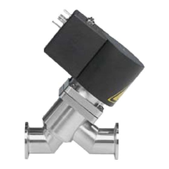
HV-Angle Valve
HV-Inline Valve
with electromagnetic actuator
single acting with closing spring (NC)
This manual is valid for the valve ordering number(s):
26...
26
4
24
-K 61
A
A ..
K ..
20.. DN 10
4 ..
The fabrication number is indicated on each product as per the label
below (or similar):
ma de in S wit zerlan d
Fab rica tion No .:
pa te nte d
2 6 . . . – . . . . – . . . . / . . . .
A – . . . . . .
Explanation of symbols:
Read declaration carefully before you start any other
action!
Attention!
Product is in conformity with EC guidelines,
if applicable!
Disconnect electrical power and compressed air
lines. Do not touch parts under voltage!
Read these «Installation, Operating & Maintenance Instructions» and the enclosed «General
Safety Instructions» carefully before you start any other action!
VAT Vakuumventile AG, CH-9469 Haag, Switzerland
Tel +41 81 771 61 61 Fax +41 81 771 48 30 CH@vatvalve.com www.vatvalve.com
Installation, Operating & Maintenance Instructions
Series 264, DN 10 - 16 (I.D. 3/8 - 5/8")
(Series 264)
(Series 265)
Aluminum
E .. Stainless Steel
ISO-KF
G .. CF-R
24 .. DN 16
Angle Valve
5 .. Inline Valve
. .
Fabrication number
Keep body parts and objects away from the valve
opening!
Hot surfaces; do not touch!
Loaded springs and/or air cushions are potential
hazards!
Wear gloves!
279114EC
2010-10-06
1/10
Advertisement
Table of Contents

Related Manuals for VAT 265 Series


Summarization of Contents
Use of Product
Product Usage Guidelines
Use product for clean and dry indoor vacuum applications under the conditions indicated in chapter «Technical data» only!
Installation and Connections
Unpacking Valve
Before unpacking the valve, make sure that the packaging is in impeccable condition and the valve has not suffered damage.
System Installation
The plastic packaging material and/or protective covers may only be removed immediately before the valve is mounted into the system.
Electrical Connections
Do not touch parts under voltage! Connect electrical power only when valve is installed into the system - moving parts cannot be touched.
Low Voltage Control
The valve requires system voltage supply at the power connector (100..115 VAC or 200..240 VAC) on the signal connector provide 20..28V DC.
Line Voltage Control
Valves are available for 100..115 VAC and 200..240 VAC (check label on valve).
Operation Under Increased Temperature
Coil of magnet can reach a temperature of 70° C when continuously used. Beware of touching!
Power Failure Behavior
Valve closes. Both position indicator relays are open, LEDs are off.
Maintenance and Repairs
Seal Replacement Procedure
The item numbers in brackets refer to the drawing on page 9.
Need help?
Do you have a question about the 265 Series and is the answer not in the manual?
Questions and answers