
Related Manuals for VAT LINVAT 070 Series


Summary of Contents for VAT LINVAT 070 Series
- Page 1 Installation, Operating & Maintenance Instructions ATM Door LINVAT Series 070 This manual is valid for the following product ordering numbers: 070__-UA24 070__-VA24 Sample picture 891111EB.DOCX Edition 2020-05-07...
- Page 2 VAT. Offenders are liable to pay damages. The original VAT firmware and updated state of the art versions of the VAT firmware are intended for use with VAT products. The VAT firmware contains a limited, time unlimited user license.
-
Page 3: Table Of Contents
Series 07 Contents Description of product ................ 4 Identification of product..................4 Use of product ....................4 Used abbreviations ..................4 Related documents..................4 Important information ..................4 Technical data ....................4 Safety ....................5 Compulsory reading material ................5 Danger levels .................... -
Page 4: Description Of Product
• Dimensional drawing Important information This symbol points to a very important statement that requires particular attention. Example: VAT disclaims any liability for damages resulting from inappropriate packaging. Technical data See product data sheet and dimensional drawing. 4/27 Edition 2020-05-07... -
Page 5: Safety
Series 07 SAFETY Safety Compulsory reading material Read this chapter prior to performing any work with or on the product. It contains important information that is significant for your own personal safety. This chapter must have been read and understood by all persons who perform any kind of work with or on the product during any stage of its serviceable life. -
Page 6: Personnel Qualifications
SAFETY Series 07 Personnel qualifications WARNING Unqualified personnel Inappropriate handling may cause serious injury or property damage. Only qualified personnel are allowed to carry out the described work. Safety labels Label Part No. Location on product Optional on the outside of T-9001-155 the actuator Table 2-1... -
Page 7: Design And Function
Series 07 DESIGN AND FUNCTION Design and Function Design 1 Gate 2 Torsion bar 3 Protection bellows (optionally) 4 Actuator 5 Compressed air connection 6 Position indicator connection Figure 3-1 891111EB.DOCX Edition 2020-05-07 7/27... -
Page 8: Function
DESIGN AND FUNCTION Series 07 Function The stroke of the two pneumatic cylinders implements two different movements of the plate. The first movement is the vertical stroke. The second movement is the horizontal stroke. The horizontal movement is driven from the same pneumatic cylinder as the vertical stroke but activated by a linear guidance. -
Page 9: Installation
• Make sure that the supplied product is in accordance with your order. • Inspect the quality of the supplied product visually. If it does not meet your requirements, please contact VAT immediately. • Store the original packaging material. It may be useful if the product must be returned to VAT. -
Page 10: Installation Into The System
INSTALLATION Series 07 Installation into the system WARNING Hazardous components Parts, loaded springs, air cushions etc. may move or release a movement and cause serious injury. Do not connect or supply electrical power and compressed air before the product is completely mounted in the system. NOTICE Contamination Product may get contaminated. - Page 11 Series 07 INSTALLATION Mount actuator onto the chamber, use the existing fixation screws (1), see «Figure 4-1». Location of screws depends on mounting position. See «Figure 4-1» on page U-Type V-Type Fixation screws Figure 4-1 Apply torque as specified on the dimensional drawing. Close the cap from the screw access point properly afterwards.
-
Page 12: Compressed Air Connection
INSTALLATION Series 07 Compressed air connection WARNING Product in open position Risk of injury when compressed air is connected to the product. Connect compressed air only when: – product is installed to the vacuum system – moving parts cannot be touched Use clean, dry or slightly oiled air only. -
Page 13: Initial Operation
Series 07 INSTALLATION Initial operation WARNING Movable parts Human body parts may get jammed and severely injured. Keep human body parts away from movable parts. L-movement requires initializing of compressed air system. The door command must be set to open at first. This will pressurize the pneumatic system and ensure the proper L-movement during the following closing cycles. -
Page 14: Operation
OPERATION Series 07 Operation WARNING Unqualified personnel Inappropriate handling may cause serious injury or property damage. Only qualified personnel are allowed to carry out the described work. WARNING Movable parts Human body parts may get jammed and severely injured. Do not operate before product is installed completely into the vacuum system. Until actuation of the door keep human body parts away from movable parts. -
Page 15: Normal Operation
Series 07 OPERATION Normal operation The door opens and closes pneumatically. Operation under increased temperature Maximum allowed temperature, see product data sheet. Behavior in case of air pressure drop See product data sheet. L-movement requires initializing of compressed air system. The door command must be set to open at first. -
Page 16: Trouble Shooting
OPERATION Series 07 Trouble shooting Failure Check Action Check seals and Clean sealing surfaces Product data sheet sealing surfaces Damage of gate Replace gate «6.3 Replacement Leak at gate of gate» Seal Check compressed air Product data sheet compression of and dimensional gate drawing... -
Page 17: Maintenance
• Influences from the process may require more frequent maintenance. • If the door has reached the specified life cycle – see product data sheet – we recommend a general overhaul by VAT. Please contact one of our service centers. You will find the contact data on our website www.vatvalve.com. -
Page 18: Replacement Of Gate
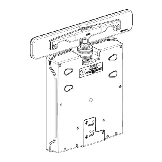
MAINTENANCE Series 07 Replacement of gate NOTICE Wrong tightening torque Door body and screws may get damaged. Use tightening torque according to size of the screws. NOTICE Contamination Product may get contaminated. Always wear cleanroom gloves when handling the product. NOTICE Inappropriate tools Sealing surfaces may get damaged. - Page 19 Series 07 MAINTENANCE 1 Convenience tool 2 Gate Figure 6-2 Exchange gate with a new gate. Grasp a new gate (2) carefully, use the convenience tool (1). 10. Install the new gate (2) carefully, use the convenience tool (1). 11. Tighten the screw for the gate (2) with a torque of 5 Nm, use torque wrench. 12.
-
Page 20: Replacement Of Gate With O-Ring
MAINTENANCE Series 07 Replacement of gate with O-ring NOTICE Wrong tightening torque Door body and screws may get damaged. Use tightening torque according to size of the screws. NOTICE Contamination Product may get contaminated. Always wear cleanroom gloves when handling the product. NOTICE Inappropriate tools Sealing surfaces may get damaged. -
Page 21: Repairs
Repairs may only be carried out by the VAT service staff. In exceptional cases, the customer is allowed to carry out the repairs, but only with the prior consent of VAT. Please contact one of our service centers. You will find the addresses on our website www.vatvalve.com. -
Page 22: Dismounting And Storage
DISMOUNTING AND STORAGE Series 07 Dismounting and Storage WARNING Unqualified personnel Inappropriate handling may cause serious injury or property damage. Only qualified personnel are allowed to carry out the described work. WARNING Hazardous components Human body parts may get jammed and severely injured. Before dismounting the product: –... -
Page 23: Dismounting
Series 07 DISMOUNTING AND STORAGE Dismounting NOTICE Sensitive product Product will get damaged if not handled carefully. Handle product with care: Do not touch solid objects when lifting the product and place it down slowly and gently. Open the door. For dismounting the door follow the steps of chapter «4 Installation», however in reverse order. -
Page 24: Packaging And Transport
• If products are radioactively contaminated, the VAT form «Contamination and Radiation Report» must be filled out. Please contact VAT in advance. • If products are sent to VAT in contaminated condition, VAT will carry out the decontamination procedure at the customer's expense. -
Page 25: Packaging
Series 07 PACKAGING AND TRANSPORT Packaging Cover the gate with protective foil. Pack product appropriately by using the original packaging material. VAT disclaims any liability for damages resulting from inappropriate packaging. Transport NOTICE Inappropriate packaging Product may get damaged if inappropriate packaging material is used. -
Page 26: Disposal
DISPOSAL Series 07 Disposal WARNING Harmful substances Environmental pollution. Discard products and parts according to the local regulations. 26/27 Edition 2020-05-07 891111EB.DOCX... -
Page 27: Spare Parts
«1.1 Identification of product». This is to ensure that the appropriate spare parts are supplied. • VAT makes a difference between spare parts that may be replaced by the customer and those that need to be replaced by the VAT service staff.
Need help?
Do you have a question about the LINVAT 070 Series and is the answer not in the manual?
Questions and answers