Table of Contents
Advertisement
Advertisement
Table of Contents

Related Manuals for Siemens 6ES7155-6AU01-0BN0


Summarization of Contents
Preface and Documentation Overview
Purpose of the Documentation
Explains the manual's role in supporting the ET 200SP system.
Conventions Used in the Manual
Details how notes, warnings, and important information are presented.
Industrial Security Information
Discusses industrial security functions and user responsibilities for secure operation.
Guide to the SIMATIC ET 200SP Documentation
Basic Information Resources
Covers system manuals and TIA Portal online help for configuration.
Device-Specific Information
Explains product manuals for module-specific details like properties and wiring.
General Topic Manuals
Refers to function manuals for general topics like diagnostics and communication.
Manual Collection ET 200SP
Describes the collection of all ET 200SP documentation in one file.
mySupport Online Portal
Details the personal workspace for online support, data requests, and libraries.
Application Examples
Highlights tools and examples for solving automation tasks.
TIA Selection Tool
Introduces a tool for selecting, configuring, and ordering devices.
SIMATIC Automation Tool
Explains a tool for commissioning and maintenance activities.
PRONETA Network Analysis
Describes a tool for PROFINET network analysis during commissioning.
SINETPLAN Network Planner
Introduces a network planner for PROFINET system dimensioning.
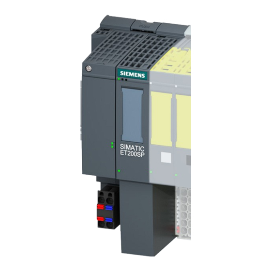
Product Overview of the IM 155-6 PN ST
2.1 Module Properties
Details the article number, module view, and technical properties of the interface module.
Maximum Configuration Limits
Outlines the limits for I/O modules, I/O data, and backplane bus.
Available Accessories
Lists accessories that can be ordered separately for the module.
Server Module Description
Describes the server module's properties and its role in the system.
First BaseUnit Configuration
Explains the use and requirements for the first BaseUnit in a configuration.
2.2 Module Functions
Introduces the PROFINET IO and additional functions supported by the interface module.
Wiring and Pin Assignments
3.1 24V DC Supply Voltage Pin Assignment
Details the pin assignment for the 24 V DC supply voltage connection.
3.2 Schematic Circuit Diagram
Provides a block diagram illustrating the IM 155-6 PN ST interface module's components.
Parameters and Address Space
4.1 Interface Module Parameters
Lists the parameters available for the IM 155-6 PN ST via GSD file.
4.2 Explanation of Configuration Control
Explains the 'Configuration control' parameter and its implications.
4.3 Substitute Value Behavior
Describes how the IO controller handles substitute values for output behavior.
4.4 Status of Supply Voltage L+
Explains how to read the status of the supply voltage L+ for I/O modules.
Interrupts, Diagnostics, Errors, and System Messages
5.1 LED Status and Error Displays
Details LED displays on the interface module and BusAdapter for status and errors.
RN/ER/MT LED Behavior
Explains the meaning and remedies for RN, ER, and MT LED status displays.
PWR LED Status
Describes the PWR LED status and its corresponding remedies.
LK1/LK2 LED Status on BusAdapter
Explains the LK1/LK2 LED status and their remedies on the BusAdapter.
LEDs for Configuration Errors
Identifies configuration errors indicated by ERROR and MAINT LEDs.
Error Type and Location Display
Details the sequence of error type and location display.
5.2 Interrupts Overview
Explains how the I/O device generates interrupts for error events.
Evaluating Interrupts with I/O Controllers
Lists supported interrupts: diagnostics, hardware, and maintenance events.
System Diagnostics in STEP 7
Describes system diagnostics available in STEP 7 (TIA Portal).
Triggering Diagnostics Interrupts
Explains how I/O modules trigger diagnostics interrupts for faults.
Triggering Hardware Interrupts
Describes how process interrupts trigger hardware interrupts.
Triggering Swapping Interrupts
Explains how swapping interrupts are processed.
5.3 Alarms and Diagnostics
Introduces alarms and diagnostics alarms.
Actions After a Diagnostics Alarm
Details actions initiated by a diagnostics alarm.
Reading Diagnostics with STEP 7
Explains how to read diagnostics using STEP 7.
Causes of Error and Troubleshooting
Refers to product manuals for error causes and remedies.
5.3.2 Maintenance Events
Discusses maintenance events for detecting potential problems.
5.3.3 Channel Diagnostics
Explains channel-related diagnostics for module faults.
Diagnostics Data Records Structure
Describes the data records based on PROFINET IO standards.
Extended Channel Diagnostics Coding
Details extended channel diagnostics reported by the module.
Manufacturer-Specific Diagnostics Structure
Explains the structure of diagnostics data records based on BlockVersion.
USI Structure for Diagnostics
Details manufacturer-specific diagnostics signaled in the USI.
USI Structure W#16#0003
Describes the USI structure for failure of supply voltage L+.
USI Structure W#16#0004
Details the USI structure for a missing server module.
USI Structure W#16#0005
Explains the USI structure for multiple pulled I/O modules.
USI Structure W#16#0006
Describes the USI structure for an I/O module on an incorrect BaseUnit.
USI Structure W#16#0007
Details the USI structure for operation not possible with existing bus configuration.
5.3.4 Invalid Configuration States
Explains invalid configuration states leading to IO device failure.
5.3.5 Supply Voltage L+ Failure
Describes how I/O modules react to supply voltage failure.
5.3.6 IO Controller STOP and Device Recovery
Explains diagnostics handling when the IO controller is in STOP.
Compatibility of IM 155-6 PN ST Versions
Version Compatibility Matrix
Compares different versions of the IM 155-6 PN ST and their functional differences.
Supply Voltage Status Validity
Explains validity of load voltage diagnostics and signaling for modules.
Compatible Modules and Article Numbers
Lists modules and their corresponding article numbers for compatibility.
Fail-Safe Module Reaction Times
Provides the formula for calculating maximum reaction times for fail-safe modules.
Technical Specifications
IM 155-6 PN ST Specifications
Lists article number, general info, product functions, and engineering requirements.
Configuration Control Details
Specifies that configuration control is available via dataset.
Supply Voltage Specifications
Details the rated and permissible ranges for the supply voltage.
Mains Buffering Information
Provides information on mains/voltage failure stored energy time.
Input Current Ratings
Lists current consumption (rated, max.) and inrush current.
Power Consumption and Loss
Specifies infeed power to backplane bus and typical power loss.
Address Space Details
Mentions address space per module and station.
Hardware Configuration Limits
Details the maximum quantity of ET 200SP and ET 200AL modules.
Submodule Capacity
States the maximum number of submodules per station.
Interface Details
Describes the number of PROFINET interfaces and ports.
PROFINET Protocols Supported
Lists PROFINET IO device protocols like IRT, PROFlenergy, and Shared device.
RJ45 Ethernet Interface Types
Details transmission procedures, speeds, and autonegotiation for RJ45.
Redundancy and Communication Modes
Specifies PROFINET system redundancy (S2) and Media redundancy (MRP).
Open IE Communication Protocols
Lists supported IE communication protocols: TCP/IP, SNMP, LLDP.
Interrupts, Diagnostics, and Status Indicators
Details status indicators, alarms, and diagnostics functions.
Diagnostics Indication LEDs
Describes the RUN, ERROR, MAINT, and PWR LEDs.
Potential Separation and Isolation
Explains potential separation, permissible difference, and isolation.
Ambient Conditions and Altitude
Lists ambient temperature ranges and maximum installation altitude.
Connection Method Details
Describes the ET-Connection method.
Module Dimensions
Provides width, height, and depth of the module.
Module Weights
States the approximate weight of the module without BusAdapter.
Dimension Drawing of the Interface Module
Figure A-1: Front and Side View Dimensions
Shows the front and side view dimensions of the module installed on a mounting rail.
Need help?
Do you have a question about the 6ES7155-6AU01-0BN0 and is the answer not in the manual?
Questions and answers