Table of Contents
Advertisement
Advertisement
Table of Contents

Related Manuals for Siemens 6ES7157-1AB00-0AB0


Summarization of Contents
Legal and Safety Information
Warning Notice System
Defines safety alert symbols and their meanings for hazard communication.
Qualified Personnel Requirements
Specifies requirements for personnel operating the product/system.
Proper Use of Siemens Products
Outlines guidelines for safe and proper operation of Siemens products.
Preface and Documentation Structure
Purpose of the Documentation
Explains the scope and content of the manual.
Manual Conventions and Notes
Describes formatting and notation conventions used in the manual.
Industrial Security Information
Provides guidance on industrial security and cyber threat protection.
Documentation Guide
General Information Resources
Covers general topics related to the ET 200AL system and its documentation.
Module-Specific Information
Details module-specific information like properties, diagrams, and technical specifications.
System Setup Guides
Covers system manual and getting started guides for configuration and commissioning.
Online Support and Tools
mySupport for Custom Manuals
Explains how to create custom manuals and compile documentation using mySupport.
mySupport for Product Data
Details accessing product data like CAD models and manuals via mySupport CAx area.
Automation Task Examples
Provides tools and examples for solving automation tasks with Siemens products.
TIA Selection Tool Overview
Introduces a tool for selecting, configuring, and ordering Siemens automation devices.
Product Overview and Properties
Interface Module Properties
Lists the key technical properties of the SIMATIC ET 200AL interface module.
Maximum Configuration Limits
Specifies the maximum configurable data and modules for the interface module.
Module Accessories and Spare Parts
Lists included, spare, and accessory components available for the module.
Operator Interface and Controls
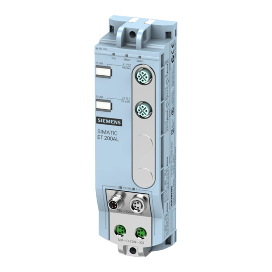
Module Indicators and Physical Controls
Describes the physical controls and LED indicators on the interface module.
Module Functions
PROFINET IO Capabilities
Explains the PROFINET IO functions supported by the interface module.
PROFINET IO Requirements
Outlines software requirements for using PROFINET IO functions with the module.
Communication Protocols and Modes
Details real-time, isochronous communication, and device replacement functionalities.
PROFlenergy Energy Saving
PROFlenergy Introduction and Purpose
Defines PROFlenergy and its operating principle for energy saving in automation systems.
PROFlenergy Operation and Control
Explains the "Pause" control mechanism, behavior, and LED indications for PROFlenergy.
PROFlenergy Error Management
Describes how errors are detected, handled, and suppressed during PROFlenergy pauses.
PROFlenergy Parameter Configuration
Explains the process of assigning parameters for PROFlenergy functionality.
PROFlenergy Data Records and Error Codes
Details PROFlenergy control data records and their associated error messages.
PROFlenergy System Integration
Covers PROFlenergy control data records and configuration control for system extensions.
Wiring and Connections
Terminal and Block Diagram
Shows the terminal and block diagram illustrating the module's connections.
PROFINET Connector Pinout
Details the pin assignments for the PROFINET sockets (X1 P1 R, X1 P2 R).
ET-Connection and Power Supply Pinout
Details pin assignments for ET-Connection sockets and power supply connectors.
Wiring Safety Guidelines
Critical Safety Warnings for Wiring
Highlights critical safety instructions for correct wiring and PROFINET IO operation.
Module Parameters and Configuration
Configuration Control Parameter
Explains the function and usage of the configuration control parameter for the module.
Status Indicators and Diagnostics
LED Status Interpretation
Details the function and meaning of the various LEDs on the interface module.
PROFINET and ET-Connection LED Status
Explains the status displays for the PROFINET (P1/P2 LINK) and ET-Connection (ET-CON1/2) LEDs.
Interrupts and Error Handling
Interrupt Evaluation Methods
Explains how interrupts are evaluated by the I/O controller and module.
Triggering System Interrupts
Details how the module triggers diagnostics, hardware, and module replacement interrupts.
System Alarms and Events
Diagnostics Alarm Actions
Details actions initiated by the module after a diagnostics alarm occurs.
Reading and Troubleshooting Diagnostics Data
Guides on how to read diagnostic data and resolve common error causes.
Maintenance Events and System Alarms
Describes maintenance events, their triggers, and related system alarms in STEP 7.
Channel Diagnostics and Error States
Provides information on channel-related diagnostics and handling of invalid configuration states.
IO Controller STOP State Diagnostics
Explains how to read diagnostics data when the IO controller is in a STOP state.
Technical Specifications
General Product and Engineering Data
Covers general product details, vendor information, firmware, and engineering software requirements.
Electrical and Power Specifications
Details supply voltage range, input current, reverse polarity protection, and power loss.
Interface and Address Space Details
Lists interface types, number of interfaces, address space, and hardware configurations.
Communication Protocols and Services
Lists supported communication protocols like PROFINET IO, TCP/IP, and their services.
LED Indicators and Electrical Isolation
Describes diagnostic LEDs, connection indicators, and electrical isolation specifications.
Environmental and Physical Characteristics
Specifies protection classes, operating ambient conditions, connection technologies, dimensions, and weight.
Dimension Drawing
Module Physical Dimensions
Illustrates the physical dimensions of the interface module with key measurements.
Cycle Time Analysis
ET-Connection Cycle Time Chart
Shows the trend of ET-Connection cycle times based on I/O module count and PROFINET send clock.
Need help?
Do you have a question about the 6ES7157-1AB00-0AB0 and is the answer not in the manual?
Questions and answers