Table of Contents
Advertisement
Interface module
15B
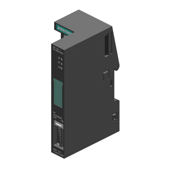
IM151-1 STANDARD
(6ES7151-1AA06-0AB0)
SIMATIC
ET 200S distributed I/O
Interface module
IM151-1 STANDARD
(6ES7151-1AA06-0AB0)
Manual
07/2015
A5E01075950-AD
___________________
Preface
___________________
Properties
___________________
Parameters
___________________
Functions
___________________
Interrupt, error, and system
messages
___________________
Response times
1
2
3
4
5
Advertisement
Table of Contents

Summarization of Contents
Legal information
Warning notice system
Defines safety alert symbols and their meanings to prevent personal injury and property damage.
Qualified Personnel
Specifies that only trained personnel should operate the product as per documentation and safety instructions.
Proper use of Siemens products
Outlines requirements for safe operation, including using approved parts and following documentation.
Preface
Purpose of the manual
Explains the manual supplements operating instructions for commissioning the ET 200S.
Basic knowledge requirements
States general knowledge of automation engineering is needed to understand the manual.
Scope of the manual
Defines the manual's applicability to the ET 200S module at the time of publication.
Recycling and disposal
Advises contacting certified companies for environmentally compliant recycling of electronic waste.
Additional support
Guides users to contact local representatives or online resources for further assistance.
Technical Support
Provides contact methods for technical support via an internet web form and additional online information.
Service & Support on the Internet
Highlights the comprehensive knowledge base, newsletter, documentation search, and contact database available online.
Properties
Properties
Lists key features of the IM151-1 STANDARD interface module, including connectivity and capabilities.
Installation constraints
Details how using certain electronic modules reduces the number of connectable I/O modules.
Terminal assignment
Shows the terminal connections for the interface module's 24 V DC voltage supply and PROFIBUS DP.
Block diagram
Illustrates the functional structure of the IM151-1 STANDARD interface module and its connections.
Technical specifications
Presents detailed technical data for the IM151-1 STANDARD, including dimensions, transmission rates, and interfaces.
Updating the firmware
Explains the process and requirements for updating the firmware of the IM151-1 STANDARD interface module.
Configuration with more than 244 bytes of parameter data
Describes configurations using STEP 7 V5.4 for DPV1 mode with extended parameter data.
Parameters
Parameters for the IM151-1 STANDARD interface module
Lists parameters, their value ranges, default settings, and applicability for the interface module.
Parameter description
Provides detailed explanations for various parameters like DP interrupt mode, bus length, and option handling.
Functions
Option handling with RESERVE modules
Explains how to use RESERVE modules for flexible configuration and future expansion of the ET 200S.
Option handling without reserve modules
Describes the principle, prerequisites, and configuration for using option handling without RESERVE modules.
Identification data
Details how to read identification data (e.g., manufacturer, revision) for module identification and system checks.
Interrupt, error, and system messages
LED displays
Describes the function of the SF, BF, and ON LEDs on the interface module for status indication.
Status and error displays
Details the meaning of LED combinations and their corresponding causes and remedies for troubleshooting.
Process interrupt lost
Explains the 'Process interrupt lost' diagnostics, its availability, and potential issues with high interrupt rates.
Diagnostic messages of the electronic modules
Outlines actions and behaviors following diagnostic messages in DPV0 and DPV1 modes, including LED indicators and CPU response.
Diagnostics with STEP 7
Explains how to read slave diagnostics using STEP 7, including frame structure, options, and SFC examples.
Evaluating the interrupts of the ET 200S
Describes how the ET 200S handles diagnostic, process, and remove/insert module interrupts in DPV1 mode.
Response times
Overview
Provides a diagram illustrating the response time relationships between the DP Master and the ET 200S.
Response times for the ET 200S
Presents an equation for calculating ET 200S response time based on module count and I/O bytes.
Response time for digital input modules
Explains that reaction times for digital inputs depend on the input delay.
Response time for digital output modules
States that response times for digital outputs correspond to the output delay.
Response time for analog input modules
Details conversion time and cycle time for analog input modules, including optimization tips.
Reaction times of analog output modules
Covers conversion time, cycle time, and settling time for analog output modules.
Response times for a 4 IQ-SENSE electronic module
Specifies response time for the 4 IQ-SENSE module as a cycle time in the Technical Data.
Response times for technology modules
Indicates that response times for technology modules are found in the Technical Data and specific manuals.


Need help?
Do you have a question about the 6ES7151-1AA06-0AB0 and is the answer not in the manual?
Questions and answers