Panasonic KV-S4065CL - Sf Clr Duplex 65PPM USB 2.0 Lgl 300PG Adf Operating Manual
High speed color scanner
Hide thumbs
Also See for KV-S4065CL - Sf Clr Duplex 65PPM USB 2.0 Lgl 300PG Adf:
- Service manual (21 pages) ,
- Specifications (2 pages) ,
- Operating manual (87 pages)
Table of Contents
Advertisement
These instructions contain information on operating the scanner. Before reading these instructions, please read
the installation manual enclosed with this unit.
Please carefully read these instructions and the enclosed installation manual. Keep all documentation in a safe
place for future reference.
KV-S4085CL / KV-S4085CW
Model No.
KV-S4065CL / KV-S4065CW
Operating Manual
High Speed Color Scanner
Advertisement
Table of Contents

Related Manuals for Panasonic KV-S4065CL - Sf Clr Duplex 65PPM USB 2.0 Lgl 300PG Adf


Summary of Contents for Panasonic KV-S4065CL - Sf Clr Duplex 65PPM USB 2.0 Lgl 300PG Adf
- Page 1 Operating Manual High Speed Color Scanner KV-S4085CL / KV-S4085CW Model No. KV-S4065CL / KV-S4065CW These instructions contain information on operating the scanner. Before reading these instructions, please read the installation manual enclosed with this unit. Please carefully read these instructions and the enclosed installation manual. Keep all documentation in a safe place for future reference.
-
Page 2: Feature Highlights
Introduction Introduction Thank you for purchasing a Panasonic High Speed Color Scanner. Feature Highlights Superior Paper Feeding • This scanner features an advance paper feeding mechanism that monitors the condition of the document and adjusts the pressure of the rollers accordingly. As a result, this scanner can scan a wide range of paper weights, from very thin 20 g/m²... -
Page 3: About The Documentation
RTIV Reference Manual Explains the features and settings for RTIV (Reliable Throughput Imaging Viewer). • PIE Reference Manual Explains the settings of the PIE (Panasonic Image Enhancement Technology) features using the ISIS and TWAIN drivers. Abbreviations • Windows refers to the Microsoft Windows operating system (hereafter Windows). -
Page 4: System Requirements
Introduction International ENERGY STAR Program As an ENERGY STAR ® Partner, Panasonic has determined that this product meets the ENERGY STAR guidelines for energy efficiency. System Requirements PC/AT or compatible machine with a CD-ROM drive Computer ® ® Intel Core™ 2 Duo, 1.8 GHz or higher ®... - Page 5 Introduction Federal Communications Commission Requirements (For United States on- Note This equipment has been tested and found to comply with the limits for a Class A digital device, pursuant to Part 15 of the FCC Rules. These limits are designed to provide reasonable protection against harmful interference when the equipment is operated in a commercial environment.
-
Page 6: Table Of Contents
Table of Contents Before You Start ..................8 For Your Safety .........................8 Safety Information (For United Kingdom only) ............11 Precautions ........................12 Location of Controls ................14 Main Unit ..........................14 Control Panel and Status Indicators ................16 Control Panel ........................16 About Status Indicators ....................18 Operation ....................19 Turning on the Scanner Power ..................19 Preparing Documents .....................20... - Page 7 Troubleshooting ......................77 Shading Adjustment .......................80 Repacking Instructions ....................81 Specifications ........................83 Index......................85 Operating Manual...
-
Page 8: Before You Start
Before You Start Before You Start For Users For Your Safety To prevent severe injury and loss of life, read this WARNING section carefully before using the unit to ensure proper and safe operation of your unit. • This section explains the graphic symbols used in this manual. - Page 9 Before You Start Do not attempt to repair the power cord, or Do not place the separation rollers or paper plug. If the power cord or plug is damaged feed rollers where small children can reach or frayed, contact an authorized service them.
- Page 10 Before You Start Installation and Relocation Operating Safeguards Do not position the unit in a location where If the unit falls down or gets damaged, turn it is unstable. the unit off, and unplug the power cord. Otherwise, it may cause fire or electric shock.
-
Page 11: Safety Information (For United Kingdom Only)
If you lose the fuse cover, the plug must not be used until a replacement cover is obtained. A replacement fuse cover can be purchased from your local Panasonic Dealer. IF THE FITTED MOULDED PLUG IS UNSUITABLE FOR THE SOCKET OUTLET IN YOUR PREMISES, THEN THE FUSE SHOULD BE REMOVED AND THE PLUG CUT OFF AND DISPOSED OF SAFELY. -
Page 12: Precautions
Do not move the unit immediately from a cold place refer to the Material Safety Data Sheet (MSDS). to a warm place. It may cause dew. Please ask your Panasonic sales company about obtaining the Material Safety Data Sheet. CD-ROM KEEP AWAY FROM FIRE. - Page 13 Before You Start Illegal Duplication Security Notice The management of documents and scanned data is It is unlawful to make duplication of certain the responsibility of the user. In particular, pay attention documents. to the following points. Duplicating certain documents may be illegal in •...
-
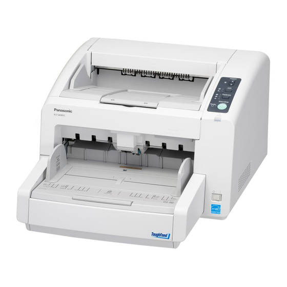
Page 14: Location Of Controls
Location of Controls Location of Controls Main Unit Front Exit document guides Exit sub stopper Exit tray Extension sub tray Exit stopper Document guides Hopper Hopper extension tray Control Panel For details, refer to "Control Panel" (page 16). 10 Error indicator Lights when an error occurs. - Page 15 Location of Controls Rear Pre-imprinter door (Exit tray) You open this door when installing an imprinter unit (sold separately) or ink cartridge. For details on installing an imprinter, refer to "Pre-imprinter" (page 67). Post-imprinter door You open this door when installing an imprinter unit (sold separately) or ink cartridge. For details on installing an imprinter, refer to "Post-imprinter"...
-
Page 16: Control Panel And Status Indicators
Location of Controls Control Panel and Status Indicators Control Panel Hopper key (Hopper) Adjusts the hopper position. See "Changing the Hopper Position" (page 23). ADF select key (ADF) Sets the feeding method to auto feeding [ ] or manual feeding [ Paper thickness key (Thickness) Changes the paper thickness mode according to the document type. - Page 17 Location of Controls Ready indicator (Ready) Shows the scanner's status. For details, see "About Status Indicators" (page 18). For details on "Manual Feed Mode", refer to the RTIV Reference Manual or PIE Reference Manual. Operating Manual...
-
Page 18: About Status Indicators
Location of Controls About Status Indicators The status of the scanner is displayed by the ready indicator ( 1 ) and the error indicator ( 2 ), as shown in the table below: 1 Ready indicator ( ) 2 Error indicator ( ) Status (Green) (Red) -
Page 19: Operation
Operation O p e r a t i o n Turning on the Scanner Power Set the power switch ( 1 ) of the scanner to " " (ON). • The ready indicator ( 2 ) lights green. Operating Manual... -
Page 20: Preparing Documents
Operation Preparing Documents Acceptable Documents The acceptable documents for this scanner are as follows. Document size 48–297 mm (1.9–11.7 in.) 70*–432 mm (2.75–17 in.) * For manual paper feed or thick paper mode: 100 mm (3.9 in.) Loadable paper thickness and number of sheets Paper thickness: Thin 20–50 g/m²... -
Page 21: Document Types
Operation Document types • • Plain paper Recycled paper • • Bond paper OCR paper • • Newspaper Bank checks • • Carbonless copy paper Tracing paper Documents must also meet the following conditions Curl Feeding direction Less than 10 mm (0.4 in.) Folding Feeding direction... -
Page 22: Unacceptable Documents
Operation Unacceptable Documents The following types of documents may not scan properly: • Torn or frayed documents • Curled, wrinkled or folded documents • Carbon paper • Thick or irregular documents such as envelopes, documents that are glued together, etc. •... -
Page 23: Paper Feed Settings
Operation Paper Feed Settings Before scanning a document, you can select the exit direction, change the hopper position, and change the paper thickness mode. Changing the Hopper Position When scanning begins, the hopper’s height is adjusted according to the amount of paper, so that the hopper is at the same level as the feeder. -
Page 24: Changing The Paper Thickness Mode
Operation Changing the Paper Thickness Mode To avoid the double feeding or jams, you can set the paper thickness mode according to the document type. Press the paper thickness key to select the desired mode. You can select the following modes: Paper Thickness Indicator When to use... -
Page 25: Selecting The Paper Path For Scanned Documents
Operation Selecting the Paper Path for Scanned Documents Scanned documents can exit from the front and back sides of the scanner. The paper path automatically switches when the straight path tray is opened or closed. Straight path tray Paper path Closed Front side (Exit tray) Opened... -
Page 26: Scanning Documents
Operation Scanning Documents This scanner can scan documents whose pages are all the same size and documents whose pages are different sizes. Notice • Make sure to remove paper clips and staples from documents before scanning. Failing to do so can damage the unit, document, or both. -
Page 27: Scanning Documents With Pages Of The Same Size
Operation Scanning Documents with Pages of the Same Size Press the ADF select key on the control panel to select auto feeding [ ] or manual feeding [ Notice • When manually feeding a document, feed the document 1 page at a time. •... - Page 28 Operation Place the documents on the hopper ( 1 ) with the side to be scanned facing up. Then push the documents in the direction of the arrow until they stop. Notice • The height of the documents should not exceed the limit mark ( 2 ) on the document guide. This may cause a paper jam or skewing.
- Page 29 Operation Slide the document guides ( 1 ) to match the width of the document to be scanned. When scanning long sheets of paper Pull out the hopper extension tray ( 2 ) from the hopper. Note • After placing the document on the hopper, if you push the Start/Stop key, the hopper will rise to a position where pages can immediately start being fed.
- Page 30 Operation Slide the exit document guides ( 1 ) to match the width of the document, and raise the exit stopper ( 2 ). Note • If you scan documents with the exit stopper ( 2 ) down, documents may jam at the exit. When scanning long sheets of paper Adjust the exit stopper ( 3 ) and extension sub tray ( 4 ) to match the size of the document.
- Page 31 Operation When scanning short sheets of paper When scanning documents like the one shown in the figure below, fully raise the exit sub stopper ( 5 ), and adjust the extension sub tray ( 6 ) to match the size of the document. Scanning direction Document When scanning thin documents...
-
Page 32: Scanning Documents With Pages Of Different Sizes
Operation Scanning Documents with Pages of Different Sizes For conditions when scanning documents with mixed page sizes, see "For documents with mixed page sizes and thicknesses" (page 21). • When scanning different size documents, scanned sheets may need to be reordered for optimum performance. - Page 33 Operation Align the document pages along one side. Completely spread apart the document guides ( 1 ). Operating Manual...
- Page 34 Operation Place the documents on the hopper ( 1 ) with the scanning side facing up. • Align the document position so that the center of the smallest sheet will be fed to the center of the paper feed rollers ( 2 ). If the document is not properly aligned, the pages will not be fed correctly. Notice •...
- Page 35 Operation While keeping the right document guide ( 1 ) in place, slide the left document guide ( 2 ) to where you will place the left edge of the document. While keeping the left document guide ( 1 ) in place, slide the right document guide ( 2 ) to match the width of the document.
- Page 36 Operation When scanning long sheets of paper Pull out the hopper extension tray ( 3 ) from the hopper. Note • After placing the document on the hopper, if you push the Start/Stop key, the hopper will rise to a position where pages can immediately start being fed.
- Page 37 Operation When scanning long sheets of paper Adjust the exit stopper ( 4 ) and extension sub tray ( 5 ) to match the largest document page. When scanning short sheets of paper When scanning documents like the one shown in the figure below, fully raise the exit sub stopper ( 6 ), and adjust the extension sub tray ( 7 ) to match the size of the document.
- Page 38 Operation When scanning thin documents Slightly raise the exit sub stopper ( 8 ). • The documents will exit smoothly since there is a smaller step at the exit. Open your scanning application and scan the documents. The software RTIV and QuickScan Pro demo, included with the scanner, can be used for scanning the documents. Note •...
-
Page 39: Using Control Sheets
Operation Using Control Sheets By using control sheets, you can change the scanning conditions in the middle of scanning. Placing a control sheet in the middle of a document lets you change the scanning conditions for all pages scanned after the control sheet. -
Page 40: About Printing Control Sheets
Operation About Printing Control Sheets • Print the control sheet at the specified size; do not enlarge or reduce the size. • When printing the control sheet, make sure that the pattern is 25 mm (1 in.) from the top of the page and centered horizontally. -
Page 41: Changing The Scan Background Color
Operation Changing the Scan Background Color By switching the reference plate on the scanner, you can change the scanning background color between black and white. The default setting is black. Notice • Set the front reference plate and rear reference plate to the same color. If the front and rear settings are different, then documents will not be scanned correctly. - Page 42 Operation Move the reference plate lever (R) ( 1 ) and the reference plate lever (F) ( 2 ). • Move the levers to the color you want to change the background to. White Black Operating Manual...
- Page 43 Operation Close the front door. • Push both sides of the front door down slowly until it clicks into place. Set the power switch of the scanner to " " (ON). Operating Manual...
-
Page 44: Care And Maintenance
Care and Maintenance Care and Maintenance Clearing Paper Jams Torn paper, thin paper or paper that is creased on the top edge may cause paper jams. If a paper jam occurs, remove the jammed sheet according to the following procedure. CAUTION •... - Page 45 Care and Maintenance When a paper jam occurs inside the scanner: Pull the jammed paper from the inside of the scanner towards the front. When a paper jam occurs at the exit slot: Pull the jammed paper from the exit slot ( 1 ) towards the front. Close the front door.
-
Page 46: Cleaning The Scanner
Care and Maintenance Cleaning the Scanner Outside of the Scanner Notice • Do not use thinner, benzine, or cleaners containing abrasives or surfactants, for cleaning the outside of the scanner. • Clean the scanner at least once a month. Set the power switch ( 1 ) of the scanner to " "... - Page 47 Care and Maintenance Remove dirt and dust from the fan exhaust vent ( 1 ) with a brush. Operating Manual...
-
Page 48: Inside Of The Scanner
Only use the roller cleaning paper to clean the rollers and image sensor covers. • For details about the roller cleaning paper, please refer to the Material Safety Data Sheet (MSDS). Please ask your Panasonic sales company about obtaining the Material Safety Data Sheet. Note •... -
Page 49: Cleaning The Rollers
Care and Maintenance Cleaning the Rollers CAUTION • When wiping the rollers (A) and the lower-section image sensor cover, make sure to close the straight path tray. Touching the notched section can cause injury. Notched section Image sensor cover Straight path tray •... - Page 50 Care and Maintenance Use the roller cleaning paper (page 48) to remove the dirt from the surfaces of all rollers. Direction to wipe rollers Double feed prevention roller, Paper feed rollers Other rollers Notice • After removing the double feed prevention roller, gently wipe dirt from the surface of the roller in the direction indicated by the arrows in the illustration.
- Page 51 Care and Maintenance Location of Rollers Paper feed rollers Separation rollers Free rollers Drive rollers Double feed prevention roller Left side view Drive rollers Operating Manual...
- Page 52 Care and Maintenance Free rollers Close the front door. • Push both sides of the front door down slowly until it clicks into place. Set the power switch of the scanner to " " (ON). Operating Manual...
- Page 53 Care and Maintenance Reset the roller cleaning counter in User Utility to 0. • Start User Utility, and in the window, click the [Clear Counter] button ( 2 ) for "After Clean Roller" ( 1 ) to reset to counter to 0. •...
-
Page 54: Cleaning The Sensors And Image Sensor Covers
Care and Maintenance Cleaning the Sensors and Image Sensor Covers CAUTION • When wiping the rollers (A) and the lower-section image sensor cover, make sure to close the straight path tray. Touching the notched section can cause injury. Notched section Image sensor cover Straight path tray... - Page 55 Care and Maintenance Remove dirt on the sensors with the included blower ( 1 ), then wipe the image sensor covers with the roller cleaning paper (page 48). How to clean the sensors and reflectors Remove the brush from the blower ( 1 ), place it on the holes for the sensors and reflectors ( 2 ), as well as the conveyor indentations ( 2 ), and blow off dirt, as shown in the illustration below.
- Page 56 Care and Maintenance Left side view Paper jam sensor Location of Reflectors Reflectors Indentations Left side view Indentations Operating Manual...
- Page 57 Care and Maintenance Open the paper feed roller cover ( 1 ), and blow off any dirt from the slip detect sensor ( 2 ) while rotating Close the front door. • Push both sides of the front door down slowly until it clicks into place. Set the power switch of the scanner to "...
-
Page 58: Replacement Parts And Optional Units
Replacement Parts and Optional Units Replacement Parts and Optional Units Replacement Parts and Optional Units Part Name Part Number Notes Roller exchange kit • Paper feed roller • KV-SS033 – Separation roller • Double feed prevention roller Replacement Parts See "About the roller cleaning pa- Roller cleaning paper KV-SS03 per"... -
Page 59: Replacing Parts
Replacement Parts and Optional Units Replacing Parts If double feeding or paper jam occurs frequently even after cleaning the roller (page 49), please call your dealer to order a "Roller exchange kit (KV-SS033)", and replace the paper feed rollers, separation rollers, and double feed prevention roller. - Page 60 Replacement Parts and Optional Units Push in both sides of the paper feed roller cover, and pull it towards you to open. Turn the roller tip ( 1 ) towards you, and remove rollers from the shaft while opening the tip. •...
- Page 61 Replacement Parts and Optional Units Push up on the paper feed roller cover until it clicks into place. Notice • When closing the paper feed roller cover, do not damage the roller. • Be sure to close the paper feed roller cover correctly. If the paper feed roller cover is not closed completely, when closing the front door, the paper feed roller cover may break.
-
Page 62: Replacing The Double Feed Prevention Roller
Replacement Parts and Optional Units Replacing the Double Feed Prevention Roller Before replacing the double feed prevention roller, make sure that the hopper is in the "Low" position. The double feed prevention roller cover cannot be opened if the hopper is not in the "Low" position. For details on adjusting the hopper’s height, see "Changing the Hopper Position"... - Page 63 Replacement Parts and Optional Units Pull open the double feed prevention roller cover towards you by using the indent ( 1 ). Remove the double feed prevention roller ( 1 ) in the direction of the arrow. Take out the new double feed prevention roller in the optional "Roller exchange kit (KV-SS033)". Operating Manual...
- Page 64 Replacement Parts and Optional Units Install the new double feed prevention roller. • Place the axis with the groove ( 1 ) facing the right side, and align the groove with the roller mount ( 2 ) to install it. Note •...
- Page 65 Replacement Parts and Optional Units Close the front door. • Push both sides of the front door down slowly until it clicks into place. Plug in the power cord, and set the power switch of the scanner to " " (ON). Operating Manual...
- Page 66 Replacement Parts and Optional Units Reset the roller replacing counter in User Utility to 0. • Start User Utility, and in the window, click the [Clear Counter] button ( 2 ) for "After Replace Roller" ( 1 ) to reset the counter to 0. •...
-
Page 67: Installing Optional Units
Replacement Parts and Optional Units Installing Optional Units Installing the Imprinter Unit You can use the imprinter as a pre-imprinter or post-imprinter, depending on your intended use. The pre-imprinter prints on the face of the document before scanning. The printed material will also be scanned. The post-imprinter prints on the rear of the document after scanning. - Page 68 Replacement Parts and Optional Units Insert the pins ( 1 ) and ( 2 ) into the upper holes until they stop, and insert the pins ( 3 ) and ( 4 ) into the guides until they are locked by the springs. Connect the cable.
- Page 69 Replacement Parts and Optional Units Close the pre-imprinter door ( 1 ). Set the power switch of the scanner to " " (ON). Note • For details on installing an ink cartridge, refer to "Installing the Ink Cartridge" (page 72). Post-imprinter Set the power switch ( 1 ) of the scanner to "...
- Page 70 Replacement Parts and Optional Units Open the post-imprinter door. Connect the cable. Notice • Be sure to correctly match the rib with the slot prior to inserting the connector. Operating Manual...
- Page 71 Replacement Parts and Optional Units While keeping the direction of the post-imprinter as shown in the diagram below, insert the pins ( 1 ) on both sides into the guides, and insert the pins ( 2 ) on both sides into the guides until they are locked by the springs ( 3 ).
-
Page 72: Installing The Ink Cartridge
Replacement Parts and Optional Units Installing the Ink Cartridge Install the ink cartridge in the imprinter. Set the power switch ( 1 ) of the scanner to " " (OFF). Remove the protective tape. Operating Manual... - Page 73 Replacement Parts and Optional Units Move the carriage to the ink cartridge exchange position. Notice • When using the pre-imprinter, adjust the position following the label on the scanner. Insert the ink cartridge into the carriage. Lock the ink cartridge adjustment lever ( 1 ). Operating Manual...
-
Page 74: Removing The Ink Cartridge
Replacement Parts and Optional Units Removing the ink cartridge Set the power switch of the scanner to " " (OFF). Move the carriage to the ink cartridge exchange position. Notice • When using the pre-imprinter, adjust the position following the label on the scanner. Pinch the ink cartridge adjustment lever ( 1 ) and lift it. -
Page 75: Printing
Replacement Parts and Optional Units Printing Adjusting the pre-imprinter printing position Locate the green line ( 1 ) on the imprinter that is aligned with the " " mark ( 2 ) on the scanner where you want to print. Align the indicator ( 3 ) with the green line ( 1 ). - Page 76 Replacement Parts and Optional Units Printing Position 141 mm (5.6 in.) 121 mm (4.8 in.) 109.3 mm (4.3 in.) 97.5 mm (3.8 in.) 97.5 mm (3.8 in.) 83.5 mm (3.3 in.) 83.5 mm (3.3 in.) 66.8 mm (2.6 in.) 66.8 mm (2.6 in.) 56.5 mm (2.2 in.) 56.5 mm (2.2 in.) 45 mm (1.8 in.)
-
Page 77: Appendix
Appendix A p p e n d i x Troubleshooting If a problem occurs while the scanner is being used, check the following items and check the scanner status with User Utility. If the scanner still malfunctions, turn it OFF, unplug the power cord and call for service. Symptom Possible Cause Remedy... - Page 78 Appendix Symptom Possible Cause Remedy The paper feed rollers, separation roll- Clean the paper feed rollers, separation ers, double feed prevention roller, drive rollers, double feed prevention roller, rollers, or free rollers are dirty. drive rollers, or free roller. (Page 49) The paper feed rollers, separation roll- Replace the paper feed rollers, separa- ers, or double feed prevention roller...
- Page 79 Appendix Symptom Possible Cause Remedy The scanned document is The document to be scanned was loa- Load the document correctly. blank. ded upside down. (Page 26) Vertical lines appear on the Clean the image sensor covers (F and The image sensor covers are dirty. scanned document.
-
Page 80: Shading Adjustment
Appendix Shading Adjustment About shading adjustment The shading adjustment function corrects variations in the lamp intensity and pixel sensor sensitivity, and reduces unevenness in density in scanned images. It can be carried out by means of the User Utility using the special shading paper, which is provided with this scanner. -
Page 81: Repacking Instructions
Appendix Repacking Instructions It is highly recommended that you keep the original carton and ALL packing materials. If you need to transport or ship the scanner, please follow these instructions. Note • Improper repacking of the scanner may result in a service charge to repair the scanner. •... - Page 82 Appendix Pack the scanner. Joint USB cable Power cord Double feed prevention roller Blower • Drivers & Utilities / Manuals CD-ROM • Installation Manual • Shading paper • Roller cleaning paper Operating Manual...
-
Page 83: Specifications
Appendix Specifications KV-S4065CL KV-S4085CL KV-S4065CW KV-S4085CW Item Scanning face Duplex Front side: Contact-type color Image Sensor (CIS) Scanning method Back side: Contact-type color Image Sensor (CIS) KV-S4065CL / KV-S4085CL: 227 mm (8.9 in.) Scanning size KV-S4065CW / KV-S4085CW: 302 mm (11.9 in.) Simplex Simplex Letter: Approx. - Page 84 Appendix KV-S4065CL KV-S4085CL KV-S4065CW KV-S4085CW Item External dimensions 474´585´329 mm (18.7´23.0´13.0 in.) (Width´Depth´Height) Weight 25 kg (55 lbs.) Power requirement AC100–240 V, 50/60 Hz Maximum 1.4 A (AC100–120 V) 1.5 A (AC100–120 V) Scanner (Scanning) 0.6 A (AC220–240 V) 0.7 A (AC220–240 V) Power con- Minimum 0.7 A (AC100–120 V)
-
Page 85: Index
Index Index Hopper key Hopper position Image control AC inlet Image sensor cover (B) ADF select key Image sensor cover (F) Imprinter unit 58, 67 Ink cartridge 58, 72 Interface Background color Blower 55, 82 Joint Cleaning the rollers Cleaning the scanner Cleaning the sensors Limit Mark 28, 34... - Page 86 Index Free rollers Paper feed rollers 51, 59 Separation rollers 51, 59 Safety information Scanning face Scanning method Scanning speed Sensors Double feed detectors Paper jam sensor Paper sensor Skew sensors Slip detect sensor Starting sensor Waiting sensor Shading adjustment Shading paper Specifications Start/Stop key...
- Page 87 For information of Compliance with EU relevant Regulatory Directives, Contact to Authorised Representative: Panasonic Testing Centre Panasonic Marketing Europe GmbH Winsbergring 15, 22525 Hamburg, Germany Panasonic Global Site http://panasonic.net/ © 2008 Panasonic Communications Co., Ltd. All Rights Reserved. PJQXC0135ZA KK0408YR0...
Need help?
Do you have a question about the KV-S4065CL - Sf Clr Duplex 65PPM USB 2.0 Lgl 300PG Adf and is the answer not in the manual?
Questions and answers