Table of Contents
Advertisement
Advertisement
Table of Contents

Related Manuals for HT MACROTESTG3


Summarization of Contents
PRECAUTIONS AND SAFETY MEASURES
Preliminary Instructions
Initial setup and usage guidelines for instrument safety.
During Use Recommendations
Guidelines for safe operation while using the instrument.
After Use Procedures
Steps to follow after completing measurements.
Measurement Categories Defined
Explanation of overvoltage categories for safe measurement selection.
GENERAL DESCRIPTION
Foreword
Introduction to the instrument models covered in the manual.
Instrument Functions Overview
Summary of the instrument's capabilities and tests.
PREPARATION FOR USE
Initial Checks and Inspection
Steps to perform before operating the instrument.
Instrument Power Supply
Information on battery types and power source management.
Storage Guidelines
Recommendations for storing the instrument.
NOMENCLATURE AND DESCRIPTION
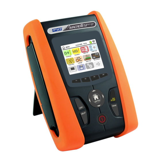
Instrument Description
Identification of instrument parts and connectors.
Measuring Leads Description
Details on the components of test leads.
Keyboard Description
Explanation of the instrument's keys and their functions.
Display Description
Details on the instrument's LCD display and touch screen.
Initial Screen Display
Information shown on the screen when the instrument starts.
GENERAL MENU AND SETTINGS
Instrument Settings Management
Configuration options for language, date/time, and system settings.
Language Setting
How to select the system language.
Reference Country Selection
Setting the reference country for measurement adjustments.
Auto Power OFF and Key Sound Config
Configuring auto power off and audible key feedback.
System Configuration
Setting electrical system type, frequency, and voltage limits.
Operator Name Entry
How to set the operator's name for measurement records.
System Date/Time Setting
Procedure for setting the instrument's date and time.
Instrument Information Display
Accessing instrument serial number, firmware, and calibration date.
OPERATING INSTRUCTIONS
6.1. RPE: Continuity of Protective Conductors
Procedure for measuring continuity of protective conductors.
6.1.1. Anomalous Situations in RPE
Handling errors or unexpected results during RPE tests.
6.2. MΩ: Insulation Resistance Measurement
Steps for measuring insulation resistance.
6.2.1. AUTO or L-PE Timer Mode
Performing insulation resistance tests in AUTO or Timer mode.
6.2.2. AUTO L/N-PE Mode
Performing insulation resistance tests between L/N-PE.
6.2.3. Anomalous Situations in Insulation Measurement
Handling errors or unexpected results during insulation tests.
6.3. RCD: Test on Differential Switches
How to perform tests on RCDs.
6.3.1. AUTO Mode for RCD Testing
Performing automatic RCD tests.
6.3.2. AUTO+ Mode for RCD Testing
Performing extended automatic RCD tests.
6.3.3. RCD Test Modes (x½, x1, x2, x5)
Using manual RCD test modes with different multipliers.
6.3.4. RCD Test with Delay Time
Testing RCDs with specific delay times.
6.3.5. RCD Ramp Test Mode
Performing ramp tests to find minimum tripping current.
6.3.6. Test on Earth Leakage Relay RCD
Testing earth leakage RCDs with optional accessory.
6.3.7. Anomalous Situations in RCD Testing
Handling errors or unexpected results during RCD tests.
6.4. LOOP: Line Impedance/Loop and Earth Resistance
Measuring line and earth loop impedance.
6.4.1. Test Types for LOOP
Overview of different loop impedance test types.
6.4.2. Test Leads Calibration (ZEROLOOP)
Calibrating test leads for accurate loop impedance measurements.
6.4.3. STD Mode – Generic Test
Performing generic loop impedance and short-circuit current tests.
6.4.4. Mode kA – Breaking Capacity Verification
Verifying the breaking capacity of protection devices.
6.4.5. Mode I²t – Short-Circuit Protection Verification
Verifying protection against short circuits using I²t parameter.
6.4.6. Mode - Protection Coordination
Testing coordination between protective devices.
6.4.7. Protection Coordination – Norway Country
Testing protection coordination specific to Norway.
6.4.8. Indirect Contacts Verification (TN System)
Verifying protection against indirect contacts in TN systems.
6.4.9. Indirect Contacts Verification (NoTrip Test)
Performing NoTrip tests for indirect contact protection.
6.4.10. Indirect Contacts Verification (UK Country)
NoTrip tests for indirect contact protection in the UK.
6.4.11. Indirect Contacts Verification (IT Systems)
Verifying protection against indirect contacts in IT systems.
6.4.12. Indirect Contacts Verification (TT Systems)
Verifying protection against indirect contacts in TT systems.
6.4.13. Impedance Measurement with IMP57 Accessory
Performing impedance measurements using the IMP57 accessory.
6.4.14. Anomalous Situations in LOOP
Handling errors or unexpected results during LOOP measurements.
6.5. SEQ: Phase Sequence and Concordance Test
Testing phase sequence and concordance.
6.5.1. Anomalous Situations in SEQ
Handling errors or unexpected results during phase sequence tests.
6.6. LEAKAGE: Leakage Current Measurement
Measuring leakage current using an external clamp.
6.7. EARTH: Measurement of Earth Resistance
Procedures for measuring earth resistance and ground resistivity.
6.7.1. 3-Wire/2-Wire Earth Measurement and 4-Wire Ground Resistivity
Methods for earth resistance and ground resistivity measurement.
6.7.2. Earth Measurement (USA, Extra Europe, Germany)
Earth resistance measurement procedures for specific regions.
6.7.3. Earth Measurement with Clamp T2100
Measuring earth resistance using the T2100 clamp accessory.
6.7.4. Anomalous Situations in Earth Resistance Measurement
Handling errors or unexpected results during earth resistance tests.
6.8. AUX: Ambient Parameter Measurement
Measuring environmental parameters using external probes.
6.9. ΔV%: Voltage Drop of Main Lines
Verifying voltage drop on main lines.
6.9.1. Anomalous Situations in Voltage Drop
Handling errors or unexpected results during voltage drop tests.
6.10. AUTO TEST: Automatic Test Sequence
Performing automatic sequences of tests (NoTrip, RCD, MΩ).
6.10.1. AutoTest in TT Systems
Performing automatic tests on TT systems.
6.10.2. AutoTest in TN Systems
Performing automatic tests on TN systems.
6.10.3. Anomalous Situations in AUTO TEST
Handling errors or unexpected results during automatic test sequences.
6.11. PQA: Real-Time Parameter Measurement
Measuring voltage, current, power, and harmonics in real-time.
6.12. EVSE: Electric Vehicle Charging Station Safety Test
Performing safety tests on EV charging stations.
EVSE System State Checks (Test 3)
Checking the internal states of EVSE systems.
EVSE Earth Resistance Measurement (Test 4)
Performing overall earth resistance measurements on EVSE systems.
EVSE RCD Type A Test (Test 5)
Testing Type A RCDs in EVSE systems.
EVSE RCD Type B Test (Test 6)
Testing Type B RCDs in EVSE systems.
OPERATIONS WITH THE MEMORY
7.1. Saving Measurements
Procedures for saving measurement data with markers and comments.
7.2. Recalling and Deleting Memory
How to retrieve and manage stored measurements.
7.2.1. Anomalous Situations in Memory Operations
Handling errors during memory management.
CONNECTING TO PC AND MOBILE DEVICES
8.1. iOS/Android Connection via WiFi
Connecting to smartphones/tablets using the HTAnalysis app.
MAINTENANCE AND SERVICE
10.1. General Maintenance Information
General guidelines for instrument care and storage.
10.2. Battery Replacement
Procedures for replacing or recharging batteries.
10.3. Instrument Cleaning
How to clean the instrument.
10.4. End of Life Disposal
Information on proper disposal of the instrument.
TECHNICAL SPECIFICATIONS
11.1. Technical Characteristics Details
Detailed specifications for various measurement functions.
11.2. Reference Guidelines and Standards
List of applicable safety and EMC standards.
11.3. General Characteristics
Physical dimensions, weight, and power supply information.
11.4. Environment
Environmental operating and storage conditions.
11.4.1. Environmental Conditions for Use
Specific environmental conditions for instrument operation.
11.5. Accessories Information
Information on available accessories.
SERVICE AND WARRANTY
12.1. Warranty Conditions
Terms and conditions of the instrument warranty.
12.2. Service and Troubleshooting
Steps to take if the instrument malfunctions.
THEORETICAL APPENDIXES
13.1. Continuity of Protective Conductors Theory
Theoretical background on continuity testing.
13.2. Insulation Resistance Theory
Theoretical principles of insulation resistance measurement.
13.3. Circuit Separation Testing Theory
Theoretical aspects of checking circuit separation.
13.4. Differential Switch (RCD) Test Theory
Theoretical basis for RCD testing.
13.5. Breaking Capacity of Protection Devices Theory
Theory behind verifying protection device breaking capacity.
13.6. Indirect Contact Protection in TN Systems Theory
Theoretical explanation of TN system indirect contact protection.
13.7. No Trip Test in TN Systems Theory
Theory behind the No Trip test in TN systems.
13.8. Indirect Contact Protection in TT Systems Theory
Theory for indirect contact protection in TT systems.
13.9. Indirect Contact Protection in IT Systems Theory
Theory for indirect contact protection in IT systems.
13.10. Protection Coordination Theory (L-N, L-PE)
Theory on coordination of protective devices.
13.11. Short-Circuit Protection (I²t) Theory
Theory for verifying protection against short circuits.
13.12. Voltage Drop on Main Lines Theory
Theoretical basis for voltage drop calculations.
13.13. Earth Resistance in TN Systems Theory
Theory for measuring earth resistance in TN systems.
13.14. Voltage and Current Harmonics Theory
Explanation of voltage and current harmonics and their causes.
13.14.1. Causes of Harmonics
Explains why voltage and current harmonics occur in power systems.
13.14.2. Consequences of Harmonics
Discusses the effects and implications of harmonic distortion.
13.15. Powers and Power Factors Calculation Theory
Formulas for calculating powers and power factors.
Need help?
Do you have a question about the MACROTESTG3 and is the answer not in the manual?
Questions and answers