Table of Contents
Advertisement
Quick Links
Advertisement
Table of Contents

Related Manuals for DEEP SEA ELECTRONICS DSECONTROL DSE7210


Summarization of Contents
Specifications
Part Numbering
Details the numbering system for DSE7000 series modules.
Model Naming
Explains the naming convention for series and functions.
Short Names
Lists short names for different module series.
Power Supply Requirements
Specifies voltage and current ratings for the module's power supply.
Terminal Specification
Details connection types and cable sizes for terminals.
Generator and Mains Voltage / Frequency Sensing
Technical parameters for voltage and frequency measurement.
Generator Current Sensing
Technical parameters for current measurement.
Digital Inputs
Specifications for digital input channels.
Analogue Inputs
Specifications for various analogue sensor inputs.
Charge Fail Input
Technical details for the charge fail input.
Magnetic Pickup
Specifications for the magnetic pickup sensor input.
Outputs A & B
Details for output relays A and B.
Outputs C & D
Details for output relays C and D.
Outputs E,F,G & H
Details for output relays E, F, G, and H.
Communication Ports
Details available communication interfaces like USB, RS232, RS485, CAN.
DSENET®
Information on the DSENet interconnection protocol.
Sounder
Details the internal sounder for alarms.
Accumulated Instrumentation
Information on logged data like engine hours and starts.
Dimensions and Mounting
Physical dimensions and panel cutout specifications.
Fixing Clips
Instructions for using fixing clips to mount the module.
Cable Tie Fixing Points
Details on using cable tie points for wiring management.
Silicon Sealing Gasket
Information on the sealing gasket for panel mounting.
Applicable Standards
Lists standards the product complies with.
Installation
User Connections
Explains icons used on the rear for terminal identification.
Terminal Description
Detailed description of each terminal's function and wiring.
DC Supply, Fuel and Start Outputs
Describes terminals for power, fuel, and start signals.
Analogue Sensor
Details terminals for analogue sensors like pressure and temperature.
Magnetic Pickup, CAN and Expansion
Describes terminals for magnetic pickup, CAN, and expansion.
Load Switching and Generator Voltage Sensing
Terminals for load control and generator voltage sensing.
Mains Voltage Sensing
Terminals for sensing mains voltage.
Generator Current Transformers
Details connections for generator current transformers (CTs).
Configurable Digital Inputs
Details terminals for configurable digital inputs.
PC Configuration Interface Connector
Describes the USB port for PC configuration.
RS485 Connector
Details the RS485 communication port.
RS232 Connector
Details the RS232 communication port.
Typical Wiring Diagrams
Provides example wiring diagrams for different module types.
7210 Autostart Controller
Wiring diagram for the 7210 autostart controller.
7220 AMF Controller
Wiring diagram for the 7220 AMF controller.
7310 Autostart Controller
Wiring diagram for the 7310 autostart controller.
7320 AMF Controller
Wiring diagram for the 7320 AMF controller.
Alternative Topologies
Details alternative AC wiring configurations.
3 Phase, 4 Wire Without Earth Fault Protection
Wiring diagram for a 3-phase, 4-wire system without earth fault.
Single Phase With Restricted Earth Fault
Wiring diagram for single-phase with restricted earth fault.
Single Phase Without Earth Fault
Wiring diagram for single-phase without earth fault.
2 Phase (L1 & L2) 3 Wire With Restricted Earth Fault
Wiring diagram for 2-phase (L1&L2) with restricted earth fault.
2 Phase (L1 & L2) 3 Wire Without Earth Fault
Wiring diagram for 2-phase (L1&L2) without earth fault.
2 Phase (L1 & L3) 3 Wire With Restricted Earth Fault
Wiring diagram for 2-phase (L1&L3) with restricted earth fault.
2 Phase (L1 & L3) 3 Wire Without Earth Fault Measuring
Wiring diagram for 2-phase (L1&L3) without earth fault measuring.
3 Phase 4 Wire With Unrestricted Earth Fault Measuring
Wiring diagram for 3-phase 4-wire with unrestricted earth fault measuring.
CT Location
Explains placement of current transformers in the system.
Description of Controls
DSE7210 / DSE7310 Autostart Control Module
Details controls and indicators for autostart modules.
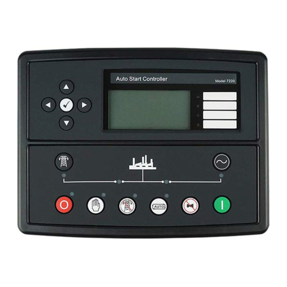
DSE7220 / DSE7320 AMF Control Module
Details controls and indicators for AMF modules.
Quickstart Guide
Provides a brief guide to starting and stopping the engine.
Starting the Engine
Step-by-step guide to start the engine.
Stopping the Engine
Step-by-step guide to stop the engine.
Viewing the Instruments
How to navigate and view instrument pages.
Instrument Page Content
Lists available data displayed on instrument pages.
CAN Error Messages
Explains how CAN engine error messages are displayed.
Viewing the Event Log
How to access and view the event log.
User Configurable Indicators
Explains the function of configurable LEDs.
Controls
Detailed explanation of each control button's function.
Operation (Standalone)
Automatic Mode of Operation
Details operation in automatic mode.
Waiting in Auto Mode
State of the module while waiting for a start request.
Starting Sequence
Steps involved in starting the engine in auto mode.
Engine Running
Engine running state and warm-up timer.
Stopping Sequence
Steps involved in stopping the engine in auto mode.
Manual Operation
Details operation in manual mode.
Waiting in Manual Mode
State of the module while waiting to start manually.
Starting Sequence
Steps involved in starting the engine manually.
Engine Running
Engine running state and load transfer in manual mode.
Stopping Sequence
Steps involved in stopping the engine manually.
Test Mode of Operation
Details operation in test mode (DSE7220/7320 only).
Waiting in Test Mode
State of the module while waiting to start in test mode.
Starting Sequence
Steps involved in starting the engine in test mode.
Engine Running
Engine running state and load transfer in test mode.
Protections
Warnings
Explains non-critical alarm conditions.
Analogue Pre-Alarms
Details alarms that warn of potential serious conditions.
High Current Warning Alarm
Warns of excessive generator output current.
Shutdowns
Lists critical alarms that stop the generator.
High Current Shutdown Alarm
Details shutdown due to prolonged high generator current.
Electrical Trips
Explains electrical trips that stop the generator.
Front Panel Configuration
Accessing the Main Front Panel Configuration Editor
How to enter the configuration editor.
Editing a Parameter
Steps to modify parameters in the editor.
Adjustable Parameters
List of configurable parameters and their factory settings.
Accessing the 'Running' Configuration Editor
How to enter the editor while the engine is running.
Editing a Parameter
Steps to modify parameters in the running editor.
Adjustable Parameters (Running Editor)
List of parameters adjustable in running mode.
Commissioning
Pre-Commissioning
Checks to perform before starting the system.
Maintenance, Spares, Repair and Servicing
Purchasing Additional Connector Plugs from DSE
How to order connector plugs.
Purchasing Additional Fixing Clips from DSE
How to order fixing clips.
Purchasing Additional Sealing Gasket from DSE
How to order sealing gaskets.
Expansion Modules
Information on compatible expansion modules.
Disposal
WEEE (Waste Electrical and Electronic Equipment)
Regulations for disposing of electronic waste.
RoHS (Restriction of Hazardous Substances)
Information on hazardous substance restrictions.
Appendix
IDMT Tripping Curves (Typical)
Graphical representation of tripping curves.
Sensor Wiring Recommendations
Guidelines for wiring various sensors.
Earth Return Sensors
Wiring recommendations for earth return sensors.
Insulated Return Sensors
Wiring recommendations for insulated return sensors.
CAN Interface
Details on using the CAN interface for engine data.
Communications Option Connections
How to connect for PC communication.
Description
Overview of PC communication via software.
PC to Controller (Direct) Connection
Steps for direct PC connection.
Enclosure Classifications
IP ratings for module enclosures.
NEMA Classifications
Approximate NEMA ratings for module enclosures.
Need help?
Do you have a question about the DSECONTROL DSE7210 and is the answer not in the manual?
Questions and answers