
Related Manuals for DEEP SEA ELECTRONICS DSEGenset DSE3110


Summary of Contents for DEEP SEA ELECTRONICS DSEGenset DSE3110
- Page 1 DEEP SEA ELECTRONICS DSE3110 Operator Manual Document Number: 057-086 Author: Ashley Senior 057-086 ISSUE: 6...
- Page 2 Deep Sea Electronics Ltd. Any reference to trademarked product names used within this publication is owned by their respective companies. Deep Sea Electronics Ltd. reserves the right to change the contents of this document without prior notice. Amendments Since Last Publication...
-
Page 3: Table Of Contents
DSE3110 Operator Manual TABLE OF CONTENTS SECTION PAGE INTRODUCTION ....................6 CLARIFICATION OF NOTATION ..................7 GLOSSARY OF TERMS ..................... 7 BIBLIOGRAPHY ......................... 8 1.3.1 INSTALLATION INSTRUCTIONS ................. 8 1.3.2 MANUALS ........................8 1.3.3 TRAINING GUIDES ...................... 8 1.3.4 THIRD PARTY DOCUMENTS ..................8 SPECIFICATIONS .................... - Page 4 DSE3110 Operator Manual 4.2.1 BACKLIGHT ....................... 29 4.2.2 ICON .......................... 29 4.2.2.1 INOPERABLE ICONS ..................29 4.2.2.2 MODE ICON ......................29 4.2.2.3 ALARM ICONS (PROTECTIONS)................ 30 4.2.3 VIEWING THE INSTRUMENT PAGES ............... 33 OPERATION ...................... 34 QUICKSTART GUIDE ....................... 34 5.1.1 STARTING THE ENGINE ...................
- Page 5 DSE3110 Operator Manual PURCHASING ADDITIONAL FIXING CLIPS FROM DSE ..........54 PURCHASING OPTIONAL SEALING GASKET FROM DSE ..........54 WARRANTY ....................55 DISPOSAL ...................... 55 11.1 WEEE (WASTE ELECTRICAL AND ELECTRONIC EQUIPMENT)........ 55 Page 5 of 56 057-086 ISSUE: 6...
-
Page 6: Introduction
Introduction 1 INTRODUCTION This document details the installation and operation requirements of the DSE3110 module. The manual forms part of the product and must be kept for the entire life of the product. If the product is passed or supplied to another party, ensure that this document is passed to them for reference purposes. -
Page 7: Clarification Of Notation
Introduction CLARIFICATION OF NOTATION Clarification of notation used within this publication. Highlights an essential element of a procedure to ensure correctness. NOTE: Indicates a procedure or practice, which, if not strictly observed, could CAUTION! result in damage or destruction of equipment. Indicates a procedure or practice, which could result in injury to personnel WARNING! or loss of life if not followed correctly. -
Page 8: Bibliography
Introduction BIBLIOGRAPHY This document refers to, and is referred by the following DSE publications which are obtained from the DSE website: www.deepseaelectronics.com or by contacting DSE technical support: support@deepseaelectronics.com. 1.3.1 INSTALLATION INSTRUCTIONS Installation instructions are supplied with the product in the box and are intended as a ‘quick start’ guide only. -
Page 9: Specifications
Specification 2 SPECIFICATIONS PART NUMBERING At the time of this document production, there are two variants of this product. 3110 Variant Product Type MPU/Hz Version Senses engine speed using MPU 3110 DSE3110 sensor or generator frequency CAN Version Senses engine speed using Hardware Revision CANbus only. -
Page 10: Terminal Specification
Specification TERMINAL SPECIFICATION NOTE: For purchasing additional connector plugs from DSE, see the section entitled Maintenance, Spares, Repair and Servicing elsewhere in this document. Description Specification Two part connector. Male part fitted to module Connection Type Female part supplied in module packing case - Screw terminal, rising clamp, no internal spring. -
Page 11: Generator Voltage & Frequency Sensing
Specification GENERATOR VOLTAGE & FREQUENCY SENSING Description Specification Measurement Type True RMS conversion Sample Rate 5 kHz or better Harmonics Up to 11 Input Impedance 300 k phase to neutral 15 V (minimum required for sensing frequency) to Phase To Neutral 333 V AC (absolute maximum) Suitable for 230 V nominal (±20 % for under/overvoltage detection) Common Mode Offset From... -
Page 12: Magnetic Pick-Up
Specification 2.7.3 MAGNETIC PICK-UP NOTE: Only applicable to 3110-xxx-01 MPU/Hz variant. Magnetic Pickup devices can often be ‘shared’ between two or more devices. For example, one device can often supply the signal to both the DSE module and the engine governor. The possibility of this depends upon the amount of current that the magnetic pickup can supply. -
Page 13: Communication Port Usage
Specification 2.9.1 COMMUNICATION PORT USAGE 2.9.1.1 USB CONNECTION (PC CONFIGURATION) NOTE: DSE stock 2 m (6.5 feet) USB type A to type B cable, DSE Part Number: 016-125. Alternatively, they are purchased from any PC or IT store. NOTE: The DC supply must be connected to the module for configuration by PC. NOTE: For further details of module configuration, refer to DSE Publication: 057-087 DSE3110 DSE Configuration Suite PC Software Manual. -
Page 14: Can Port (J1939)
Specification 2.9.1.2 CAN PORT (J1939) NOTE: Only applicable to 3110-xxx-02 CAN variant. NOTE: For further details of module configuration, refer to DSE Publication: 057-087 DSE3110 DSE Configuration Suite PC Software Manual. NOTE: For further details on connection to electronic engines, refer to DSE Publication: 057-004 Electronic Engines And DSE Wiring NOTE: Screened 120 ... -
Page 15: Dimensions And Mounting
Specification 2.11 DIMENSIONS AND MOUNTING 2.11.1 DIMENSIONS 99 mm x 79 mm x 41.5 mm (3.90 ” x 3.11 ” x 1.63 ”) 2.11.2 PANEL CUTOUT 80 mm x 68 mm (3.15 ” x 2.86 ”) 2.11.3 WEIGHT 0.09 kg (0.20 lb) Page 15 of 56 057-086 ISSUE: 6... -
Page 16: Fixing Clips
Specification 2.11.4 FIXING CLIPS NOTE: In conditions of excessive vibration, mount the module on suitable anti-vibration mountings. The module is held into the panel fascia using the supplied fixing clips. • Withdraw the fixing clip screw (turn anticlockwise) until only the pointed end is protruding from the clip. -
Page 17: Silicon Sealing Gasket
Specification 2.11.5 OPTIONAL SILICON SEALING GASKET NOTE: For purchasing an additional silicon gasket from DSE, see the section entitled Maintenance, Spares, Repair and Servicing elsewhere in this document. The optional silicon gasket provides improved sealing between module and the panel fascia. The gasket is fitted to the module before installation into the panel fascia. -
Page 18: Applicable Standards
Specification 2.12 APPLICABLE STANDARDS Standard Description BS 4884-1 This document conforms to BS4884-1 1992 Specification for presentation of essential information. BS 4884-2 This document conforms to BS4884-2 1993 Guide to content BS 4884-3 This document conforms to BS4884-3 1993 Guide to presentation BS EN 60068-2-1 -30 C (-22 F) (Minimum temperature) - Page 19 71 – Level Switch 74 – Alarm Relay 81 – Frequency Relay 86 – Lockout Relay In line with our policy of continual development, Deep Sea Electronics, reserve the right to change specification without notice. Page 19 of 56 057-086 ISSUE: 6...
-
Page 20: Enclosure Classifications
Specification 2.12.1 ENCLOSURE CLASSIFICATIONS 2.12.1.1 IP CLASSIFICATIONS The modules specification under BS EN 60529 Degrees of protection provided by enclosures IP65 (Front of module when module is installed into the control panel with the optional sealing gasket). IP42 (front of module when module is installed into the control panel WITHOUT being sealed to the panel) First Digit Second Digit Protection against contact and ingress of solid objects... -
Page 21: Installation
Installation 3 INSTALLATION The module is designed to be mounted on the panel fascia. For dimension and mounting details, see the section entitled Specification, Dimension and mounting elsewhere in this document. USER CONNECTIONS NOTE: Availability of some terminals depends upon module version. Full details are given in the section entitled Terminal Description elsewhere in this manual. -
Page 22: Connection Descriptions
Installation CONNECTION DESCRIPTIONS 3.2.1 DC SUPPLY, DC OUTPUTS A TO D & CHARGE FAIL INPUT NOTE: For further details of module configuration, refer to DSE Publication: 057-087 DSE3110 DSE Configuration Suite PC Software Manual. NOTE: When the module is configured for operation with an electronic engine, FUEL and START output requirements may be different. -
Page 23: Magnetic Pick-Up And Digital Inputs (3110-Xxx-01)
Installation 3.2.3 MAGNETIC PICK-UP AND DIGITAL INPUTS (3110-XXX-01) NOTE: For further details of module configuration, refer to DSE Publication: 057-087 DSE3110 DSE Configuration Suite PC Software Manual. Cable Description Notes Size 0.5 mm² Magnetic Pickup Positive Connect To Magnetic Pickup Device AWG 20 0.5 mm²... -
Page 24: Pc Configuration Interface Connector
Typically, they extend USB up to 50 m (55 yards). The supply and support of this type of equipment is outside the scope of Deep Sea Electronics. CAUTION!: Care must be taken not to overload the PCs USB system by connecting more than the recommended number of USB devices to the PC. -
Page 25: Typical Wiring Diagram
Installation TYPICAL WIRING DIAGRAM As every system has different requirements, these diagrams show only a typical system and do not intend to show a complete system. Genset manufacturers and panel builders may use these diagrams as a starting point; however, refer to the completed system diagram provided by the system manufacturer for complete wiring detail. -
Page 26: Earth Systems
Installation 3.3.1 EARTH SYSTEMS 3.3.1.1 NEGATIVE EARTH The typical wiring diagrams located within this document show connections for a negative earth system (the battery negative connects to Earth) 3.3.1.2 POSITIVE EARTH When using a DSE module with a Positive Earth System (the battery positive connects to Earth), the following points must be followed: •... -
Page 27: Description Of Controls
Description Of Controls 4 DESCRIPTION OF CONTROLS CAUTION: The module may instruct an engine start event due to external influences. Therefore, it is possible for the engine to start at any time without warning. Prior to performing any maintenance on the system, it is recommended that steps are taken to remove the battery and isolate supplies. -
Page 28: Control Push-Buttons
Description Of Controls CONTROL PUSH-BUTTONS Icon Description Stop/Reset Mode This button places the module into its Stop/Reset Mode . This clears any alarm conditions for which the triggering criteria have been removed. If the engine is running and the module is put into Stop mode, the module automatically instructs the generator to unload (Close Gen becomes inactive (if used)). -
Page 29: Module Display
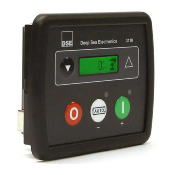
Description Of Controls MODULE DISPLAY The module’s display contains the following sections. Description of each section are viewed in the sub sections. FPE No. Instrumentation Icon Value Unit Example of DSE3110 Display 1500 rpm 4.2.1 BACKLIGHT The LCD backlight is on if the unit has sufficient voltage while the unit is turned on, unless the unit is cranking for which the backlight is turned off. -
Page 30: Alarm Icons (Protections)
Description Of Controls 4.2.2.3 ALARM ICONS (PROTECTIONS) When an alarm is active present, an alarm icon is displayed in the Icon section indicate the nature of the fault. In the event of a warning alarm, the LCD only displays the Alarm Icon. In the event of an electrical trip or shutdown alarm, the module displays the Alarm Icon and the Fault LED begins to flash. - Page 31 Description Of Controls 4.2.2.3.1 WARNING ALARM ICONS Warnings are non-critical alarm conditions and do not affect the operation of the generator system, they serve to draw the operators’ attention to an undesirable condition. Warning alarms are self-resetting when the fault condition is removed. Icon Fault Description...
- Page 32 Description Of Controls 4.2.2.3.3 SHUTDOWN ALARM ICONS Shutdown alarms are latching and immediately stop the Generator. On initiation of the shutdown condition the module de-energises the Close Gen output to remove the load from the generator. Once this has occurred, the module shuts the generator set down immediately to prevent further damage. The alarm must be accepted and cleared, and the fault removed to reset the module.
-
Page 33: Viewing The Instrument Pages
Description Of Controls 4.2.3 VIEWING THE INSTRUMENT PAGES It is possible to scroll through the display to view different pages of information by repeatedly operating the Down navigation button. Once selected, the i page remains on the LCD display until the user selects a different page. Engine Speed 1500 rpm Press the Down... -
Page 34: Operation
Operation 5 OPERATION NOTE: The following descriptions detail the sequences followed by a module containing the standard ‘factory configuration’. Always refer to the configuration source for the exact sequences and timers observed by any particular module in the field. QUICKSTART GUIDE This section provides a quick start guide to the module’s operation. -
Page 35: Stopping The Engine
Operation 5.1.2 STOPPING THE ENGINE NOTE: For further details, see the section entitled Operation elsewhere in this manual. Select Stop/Reset mode. The generator is stopped. Page 35 of 56 057-086 ISSUE: 6... -
Page 36: Stop/Reset Mode
Operation STOP/RESET MODE NOTE: If a digital input configured to External Panel Lock is active, changing module modes is not possible. Viewing the instruments is NOT affected by panel lock. Stop/Reset Mode is activated by pressing the Stop/Reset Mode button. The Stop/Reset icon is displayed to indicate Stop/Reset Mode operations. -
Page 37: Automatic Mode
Operation AUTOMATIC MODE NOTE: If a digital input configured to External Panel Lock is active, changing module modes is not possible. Viewing the instruments is NOT affected by panel lock. Auto Mode is activated by pressing the Auto Mode button. The Auto Mode icon is displayed to indicate Auto Mode operations if no alarms are present. -
Page 38: Engine Running
Operation 5.3.3 ENGINE RUNNING NOTE: The Close Gen remain inactive until the Oil Pressure has risen. This prevents excessive wear on the engine. Once the engine is running and all starting timers have expired, the animated Engine Running icon is displayed. Once the generator is available, it is then placed on load (Close Gen output becomes active (if used)) if requested. -
Page 39: Manual/Start Mode
Operation MANUAL/START MODE NOTE: If a digital input configured to External Panel Lock is active, changing module modes is not possible. Viewing the instruments is NOT affected by panel lock. To begin the starting sequence, press the Manual/Start Mode button. If Protected Start is disabled, the start sequence begins immediately. -
Page 40: Starting Sequence
Operation 5.4.2 STARTING SEQUENCE NOTE: There is no Start Delay in this mode of operation. The fuel relay is energised, and the engine is cranked. NOTE: With the 3110-xxx-02 CAN variant, compatible ECU’s receive the start command via CAN and transmit the engine speed to the DSE controller. If the engine fails to fire during this cranking attempt then the starter motor is disengaged for the Crank Rest duration after which the next start attempt is made. -
Page 41: Stopping Sequence
Operation 5.4.4 STOPPING SEQUENCE In Manual/Start Mode the set continues to run until either: • The Stop/Reset Mode button is pressed – The Close Gen output is de-activated immediately and the set immediately stops. • The Auto Mode button is pressed. The set observes all Auto Mode start requests and stopping timers before beginning the Auto Mode Stopping Sequence. -
Page 42: Front Panel Configuration
Front Panel Configuration 6 FRONT PANEL CONFIGURATION NOTE: Depending upon module configuration, some values in the Front Panel Configuration Editors may not be available. For further details of module configuration, refer to DSE Publication: 057-087 DSE3110 DSE Configuration Suite PC Software Manual. This configuration mode allows the operator to fully configure the module through its display without the use of the DSE Configuration Suite PC Software. -
Page 43: Accessing & Operating The Front Panel Editors
Front Panel Configuration ACCESSING & OPERATING THE FRONT PANEL EDITORS NOTE: For further details of module configuration, refer to DSE Publication: 057-087 DSE3110 DSE Configuration Suite PC Software Manual. 6.1.1 ENTERING THE EDITORS • Press the Stop/Reset Mode and Navigation buttons together to enter the editor mode. -
Page 44: Adjustable Parameters In Configuration Editor
Front Panel Configuration ADJUSTABLE PARAMETERS IN CONFIGURATION EDITOR 6.2.1 MODULE SETTINGS MPU/Hz 3110-xxx-01 (MPU/Hz) option only 3110-xxx-02 (CAN) option only Configuration Parameters – Module (Page 1) Contrast 000 % RESERVED RESERVED Lamp Test at Start-up On (1), Off (0) Power Save Mode Enable On (1), Off (0) Protected Start Enabled On (1), Off (0) -
Page 45: Digital Input Settings
Front Panel Configuration 6.2.3 DIGITAL INPUT SETTINGS MPU/Hz 3110-xxx-01 (MPU/Hz) option only 3110-xxx-02 (CAN) option only Configuration Parameters – Digital Inputs (Page 3) Low Oil Pressure Enable On (1), Off (0) Low Oil Pressure Trip 0.00 Bar / PSI High Engine Temperature Trip 0 ºC / ºF Digital Input A Source 0 (Input Source) -
Page 46: Timer Settings
Front Panel Configuration 6.2.5 TIMER SETTINGS Configuration Parameters – Timers (Page 5) Remote Start Delay Preheat Timer RESERVED RESERVED Smoke Limiting Smoke Limiting Off RESERVED Warm Up Time Return Delay Cooling Time ETS Solenoid Hold RESERVED RESERVED RESERVED Breaker Trip Pulse Breaker Close Pulse 6.2.6 GENERATOR SETTINGS... -
Page 47: Engine Settings
Front Panel Configuration 6.2.7 ENGINE SETTINGS MPU/Hz 3110-xxx-01 (MPU/Hz) option only 3110-xxx-02 (CAN) option only Configuration Parameters – Engine (Page 7) Magnetic Pickup Fitted On (1), Off (0) MPU/Hz Flywheel Teeth MPU/Hz Start Attempts RESERVED RESERVED MPU/Hz Gas Choke Timer (Gas Engine Only) 0:00 MPU/Hz Gas On Delay (Gas Engine Only) -
Page 48: Selectable Parameter Settings
Front Panel Configuration SELECTABLE PARAMETER SETTINGS 6.3.1 OUTPUT SOURCES MPU/Hz 3110-xxx-01 (MPU/Hz) option only 3110-xxx-02 (CAN) option only Output Sources Not Used RESERVED RESERVED RESERVED RESERVED RESERVED CAN ECU Data Fail CAN ECU Error CAN ECU Fail CAN ECU Power CAN ECU Stop RESERVED Close Gen Output... -
Page 49: Input Sources
Front Panel Configuration 6.3.2 INPUT SOURCES Input Source User Configured RESERVED Alarm Mute RESERVED Alarm Reset Alternative Configuration Coolant Temperature Switch Emergency Stop External Panel Lock RESERVED Generator Closed Auxiliary RESERVED Lamp Test Low Fuel Level Switch Oil Pressure Switch Remote Start Off Load Remote Start On Load Smoke Limiting... -
Page 50: Digital Output Polarity
Front Panel Configuration 6.3.7 DIGITAL OUTPUT POLARITY Output Polarity Index Polarity Energise De-Energise 6.3.8 CAN DATA FAIL ALARM ACTION CAN Data Fail Action Index Type None Shutdown Latched Warning 6.3.9 CAN DATA FAIL ALARM ARMING CAN Data Fail Arming Index Arming From Safety On From Starting... -
Page 51: Commissioning
Commissioning 7 COMMISSIONING Before the system is started, it is recommended that the following checks are made:- • The unit is adequately cooled and all the wiring to the module is of a standard and rating compatible with the system. Check all mechanical parts are fitted correctly and that all electrical connections (including earths) are sound. -
Page 52: Fault Finding
Fault Finding 8 FAULT FINDING NOTE: The below fault finding is provided as a guide check-list only. As the module can be configured to provide a wide range of different features, always refer to the source of the module configuration if in doubt. 8.1 STARTING Symptom Possible Remedy... -
Page 53: Alarms
Fault Finding 8.3 ALARMS Symptom Possible Remedy Check engine oil pressure. Check oil pressure switch/sensor and Low Oil Pressure operates wiring. Check configured polarity (if applicable) is correct (i.e. after engine has fired Normally Open or Normally Closed) or that sensor is compatible with the module and is correctly configured. -
Page 54: Maintenance, Spares, Repair And Servicing
Maintenance, Spares, Repair And Servicing 9 MAINTENANCE, SPARES, REPAIR AND SERVICING The controller is Fit and Forget. As such, there are no user serviceable parts within the controller. In the case of malfunction, contact the original equipment manufacturer (OEM). PURCHASING ADDITIONAL CONNECTOR PLUGS FROM DSE If additional plugs are required from DSE, contact our Sales department using the part numbers below. - Page 55 Warranty and Disposal 10 WARRANTY DSE provides limited warranty to the equipment purchaser at the point of sale. For full details of any applicable warranty, refer to the original equipment supplier (OEM). 11 DISPOSAL 11.1 WEEE (WASTE ELECTRICAL AND ELECTRONIC EQUIPMENT) If electrical and electronic equipment is used, it must be stored, collected, treated, recycled and disposed of WEEE separately from other waste.
- Page 56 This Page is Intentionally Blank...
Need help?
Do you have a question about the DSEGenset DSE3110 and is the answer not in the manual?
Questions and answers
Welke kontakten op de DSE3110 zijn beschikbaar voor het aansluiten van de temperatuursensor en de oliedruksensor? En hoe deze dan te programeren?
The DEEP SEA ELECTRONICS DSE3110 module has fully configurable inputs that can be used for various functions, including connection of temperature and oil pressure sensors. These inputs can be programmed using a PC with the DSE Configuration Suite software or directly through the module’s front panel configuration editor.
This answer is automatically generated