
Related Manuals for DEEP SEA ELECTRONICS DSEControl DSEE050


Summary of Contents for DEEP SEA ELECTRONICS DSEControl DSEE050
- Page 1 DEEP SEA ELECTRONICS DSEE050 Operator Manual Document Number: 057-300 Author: Anthony Manton 057-300 ISSUE: 1.1...
- Page 2 Deep Sea Electronics Ltd. Any reference to trademarked product names used within this publication is owned by their respective companies. Deep Sea Electronics Ltd reserves the right to change the contents of this document without prior notice. Amendments Since Last Publication Amd.
-
Page 3: Table Of Contents
DSEE050 Operator Manual TABLE OF CONTENTS Section Page INTRODUCTION ....................5 CLARIFICATION OF NOTATION .................... 6 GLOSSARY OF TERMS ......................6 BIBLIOGRAPHY ........................7 1.3.1 INSTALLATION INSTRUCTIONS ..................7 1.3.2 MANUALS ......................... 7 1.3.3 TRAINING GUIDES ......................7 SPECIFICATION ....................8 OPERATING TEMPERATURE .................... - Page 4 DSEE050 Operator Manual PCAN-USB CONNECTION DETAILS ................... 34 WARRANTY ...................... 35 DISPOSAL ......................35 WEEE (WASTE ELECTRICAL AND ELECTRONIC EQUIPMENT) ........35 057-300 ISSUE: 1.1 Page 4 of 36...
-
Page 5: Introduction
Introduction 1 INTRODUCTION This document details the installation and operation requirements of the DSEE050 module and is part of the DSEControl® range of products. The manual forms part of the product and should be kept for the entire life of the product. If the product is passed or supplied to another party, ensure that this document is passed to them for reference purposes. -
Page 6: Clarification Of Notation
Introduction 1.1 CLARIFICATION OF NOTATION Clarification of notation used within this publication. Highlights an essential element of a procedure to ensure correctness. NOTE: Indicates a procedure or practice, which, if not strictly observed, could CAUTION! result in damage or destruction of equipment. Indicates a procedure or practice, which could result in injury to WARNING! personnel or loss of life if not followed correctly. -
Page 7: Bibliography
Introduction Term Description USB to CAN converter interface for Windows™ PCs. See section entitled PCAN-USB Maintenance, Spares, Repair and Servicing elsewhere in this document for part number details. Parameter Group Number A CAN address for a set of parameters that relate to the same topic and share the same transmission rate. -
Page 8: Specification
Specification 2 SPECIFICATION 2.1 OPERATING TEMPERATURE Module Specification DSEE050 -40 ºC +85 ºC (-40 ºF +185 ºF) 2.2 TERMINAL SPECIFICATION Description Specification Connection Type Two-part connector. Male part fitted to module Female part supplied in module packing case. Minimum Cable Size 0.5 mm²... -
Page 9: Vref Output
Specification 2.4 VREF OUTPUT Provides a supply output for use with external sensors. Description Specification Applicable Pins A13, A17 5 V / 10 V configurable by DSE Configuration Suite PC Voltage Output Software. Accuracy ± 5 % Maximum Source current 100 mA Voltage Feedback 0 V to 10.8 V... -
Page 10: Analogue Current
Specification 2.5.3 ANALOGUE CURRENT Description Specification Applicable Pins A5, A6, A12, A18 Input range 0 mA to 20 mA nominal (22 mA max) Resolution 12 bits Accuracy ± 1 % FSD Precision 0.2 % FSD 150 Ω ± 1 % Input Resistance Max Common Mode Range Transient Over/Undervoltage... -
Page 11: Display Backlight
Specification 2.7 FASCIA 2.7.1 DISPLAY Description Specification Type Optically Bonded T.F.T with A.R. Coating. 3.5 “ Size Resolution 320 pixels X 240 pixels Colour Depth 16-bit colour, RGB interface 2.7.1.1 DISPLAY BACKLIGHT Device State Display Backlight State On, Normal Operating As configured (Factory Setting 80 %) Conditions Low Power/Sleep Mode... -
Page 12: Can
Specification 2.8 CAN NOTE: For further details of module configuration, refer to DSE Publication: 057-299 DSEE050 Configuration Suite PC Software Manual. NOTE: DSE Stock and supply PCAN-USB IPEH-002021. DSE Part number 016-179. Contact sales@deepseaelectronics.com. The CAN port is used for two functions: 1. -
Page 13: Dimensions And Mounting
Specification 2.9 DIMENSIONS AND MOUNTING 2.9.1 DIMENSIONS Page 13 of 36 057-300 ISSUE: 1.1... -
Page 14: Panel Cutout
Specification 2.9.2 PANEL CUTOUT 82 mm (3.23 “) hole is suitable. Maximum Panel Thickness: 6 mm (0.24 “) If a punch or milling machine is available, adding ‘flats’ at 74 mm (2.91 “) spacing serves to prevent rotation of the device in the panel cut-out. 057-300 ISSUE: 1.1 Page 14 of 36... -
Page 15: Weight
EMC Generic Emission Standard (Industrial) BS EN 60529 (Degrees of IP67 front and rear protection provided by enclosures) In line with our policy of continual development, Deep Sea Electronics, reserve the right to change specification without notice. Page 15 of 36 057-300 ISSUE: 1.1... -
Page 16: Enclosure Classifications
Specification 2.10.1 ENCLOSURE CLASSIFICATIONS 2.10.1.1 IP CLASSIFICATIONS The modules specification under BS EN 60529 Degrees of protection provided by enclosures IP67 (Front of module when module is installed into the control panel with the optional sealing gasket). IP67 (front of module when module is installed into the control panel WITHOUT being sealed to the panel) First Digit Second Digit Protection against contact and ingress of solid... -
Page 17: Installation
Installation 3 INSTALLATION The module is designed to be mounted on the panel fascia. For dimension and mounting details, see the section entitled Dimension and Mounting elsewhere in this document. 3.1 CONNECTION DESCRIPTIONS NOTE: Screened 120 impedance cable specified for use with CAN must be used for the CAN links. -
Page 18: Typical Wiring Diagram
Installation 3.2 TYPICAL WIRING DIAGRAM NOTE: As systems have differing requirements, these diagrams show only a typical system and do not intend to show a complete system. NOTE: This diagram shows connection to a Negative Earth system. For Positive Earth and Floating Earth systems, see section entitled Earth Systems elsewhere in this document. -
Page 19: Earth Systems
Installation 3.2.1 EARTH SYSTEMS 3.2.1.1 NEGATIVE EARTH The typical wiring diagrams located within this document show connections for a negative earth system (the battery negative connects to Earth). 3.2.1.2 POSITIVE EARTH When using a DSE module with a Positive Earth System (the battery positive connects to Earth), the following points must be followed: Follow the typical wiring diagram as normal for all sections except the earth points. -
Page 20: Typical Arrangement Of Can Link
Installation 3.2.2 TYPICAL ARRANGEMENT OF CAN LINK NOTE: For further details of module configuration, refer to DSE Publication: 057-299 DSEE050 Configuration Suite PC Software Manual. NOTE: Screened 120 impedance cable specified for use with CAN must be used for the CAN connection. -
Page 21: Operation
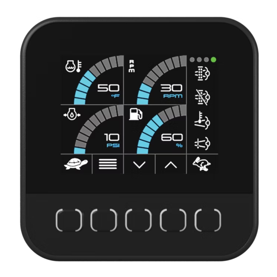
Commissioning 4 OPERATION 4.1 FASCIA Instrumentation Area Icons Area Button Idents Buttons 4.1.1 BUTTONS NOTE: This section documents the Factory (Default) settings of the DSEE050. Due to the configurable nature of the device this is subject to change as required by the supplier. Contact supplier or consult the device configuration source for full details of the configured instrumentation. -
Page 22: Instrumentation
Commissioning 4.1.2 INSTRUMENTATION NOTE: This section documents the Factory (Default) settings of the DSEE050. Due to the configurable nature of the device this is subject to change as required by the supplier. Contact supplier or consult the device configuration source for full details of the configured instrumentation. - Page 23 Commissioning Page 2 - Engine Page Display Description Engine Coolant Temperature Engine Intake Manifold Pressure Engine Intake Manifold Temperature Engine Exhaust Temperature Engine Oil Temperature Page 3 - Fuel Page Display Description Fuel Temperature Fuel Rate Fuel Pressure Page 3 – DPF and Aftertreatment Page Display Description DPF1 (Diesel Particulate Filter) Soot Percentage...
-
Page 24: Diagnostic Trouble Codes (Dtcs)
Commissioning 4.1.2.2 DIAGNOSTIC TROUBLE CODES (DTCS) NOTE: For a full list of all SPN/FMI and their detailed descriptions, consult SAE J1939 specification or consult the manufacturer/supplier of the ECU connected. When available Diagnostic Trouble Codes (DTCs) are displayed. Press to cycle through the available DTCs. - Page 25 Commissioning Common SPNs NOTE: For a full list of all SPN/FMI and their detailed descriptions, consult SAE J1939 specification or consult the manufacturer/supplier of the ECU connected. Description Engine Oil Pressure Engine Intake Manifold 1 Pressure Engine Intake Manifold 1 Temperature Engine Coolant Temperature Engine Exhaust Temperature Engine Oil Temperature...
-
Page 26: Display Brightness
Commissioning 4.1.2.3 DISPLAY BRIGHTNESS NOTE: For further details of module configuration, refer to DSE Publication: 057-299 DSEE050 Configuration Suite PC Software Manual. Allows further adjustment of the display brightness away from the value configured using DSE Configuration Suite PC Software. The chosen brightness is maintained over a power cycle of the device. -
Page 27: Device Information
Commissioning 4.1.2.4 DEVICE INFORMATION NOTE: For further details of module configuration, refer to DSE Publication: 057-299 DSEE050 Configuration Suite PC Software Manual. Displays information about the device. Description Shows the device firmware version Shows the baud rate setting for the device CAN interface. -
Page 28: Icons
Commissioning 4.1.3 ICONS NOTE: This section documents the Factory (Default) settings of the DSEE050. Due to the configurable nature of the device this is subject to change as required by the supplier. Contact supplier or consult the device configuration source for full details of the configured Icons. 4.1.3.1 LAMPS NOTE: Diagnostic Lamps are enabled/disabled by the system installer. -
Page 29: Icons
Commissioning 4.1.3.2 ICONS NOTE: This section documents the Factory (Default) settings of the DSEE050. Due to the configurable nature of the device this is subject to change as required by the supplier. Contact supplier or consult the device configuration source for full details of the configured Icons. NOTE: The Factory Settings for the Icons rely on Factory Settings for the relevant SPNs within CAN Receive. - Page 30 Commissioning Display Description CAN data is not received. The following additional actions are taken: • All CAN instrumentation changes to display # # # #. • TSC1 (Speed Control) messages are disabled (if enabled). • Outputs return to their default state as specified in the configuration. Factory Setting –...
-
Page 31: Fault Finding
Commissioning 5 FAULT FINDING NOTE: For further details of DSEE050 Configuration, refer to DSE Publication 057-299 DSEE050 Configuration Suite PC Software Manual. Issue Check Display and buttons are not If Power Saving is enabled within the device configuration, illuminated. the backlight and button lights are extinguished after a (configurable) delay. - Page 32 Fault Finding Issue Check The engine shut down with a fault If the ECU powers down after a fault shutdown, DM1s are displaying. However, upon moved to the DM2 list and cleared from the DM1 list. As such they appear as ‘grey’ colour to show they are DM1s. repowering the ECU, there are no DTCs present in the DM1 list.
-
Page 33: Maintenance, Spares, Repair And Servicing
Maintenance, Spares, Repair & Servicing 6 MAINTENANCE, SPARES, REPAIR AND SERVICING The controller is Fit and Forget. As such, there are no user serviceable parts within the controller. In the case of malfunction, you should contact your original equipment manufacturer (OEM). Description DSE Part Manufacturer Part... -
Page 34: Dsee050 Configuration Harness (016-177)
Maintenance, Spares, Repair & Servicing 6.2 DSEE050 CONFIGURATION HARNESS (016-177) NOTE: DSEE050 Configuration Harness 016-177 must be used in conjunction with Peak Systems USB CAN interface IPEH-002021 or IPEH-002022 from https://www.peak-system.com DSE Part 016-177 consists of a minimal cable with connector fitted at one end with DC supply wires and DE9 CAN connector at the other end. - Page 35 Warranty and Disposal 7 WARRANTY DSE Provides limited warranty to the equipment purchaser at the point of sale. For full details of any applicable warranty, refer to the original equipment supplier (OEM) 8 DISPOSAL 8.1 WEEE (WASTE ELECTRICAL AND ELECTRONIC EQUIPMENT) If you use electrical and electronic equipment you must store, collect, treat, recycle and dispose of WEEE separately from your other waste Page 35 of 36...
- Page 36 This Page is Intentionally Blank...
Need help?
Do you have a question about the DSEControl DSEE050 and is the answer not in the manual?
Questions and answers