Advertisement
Quick Links
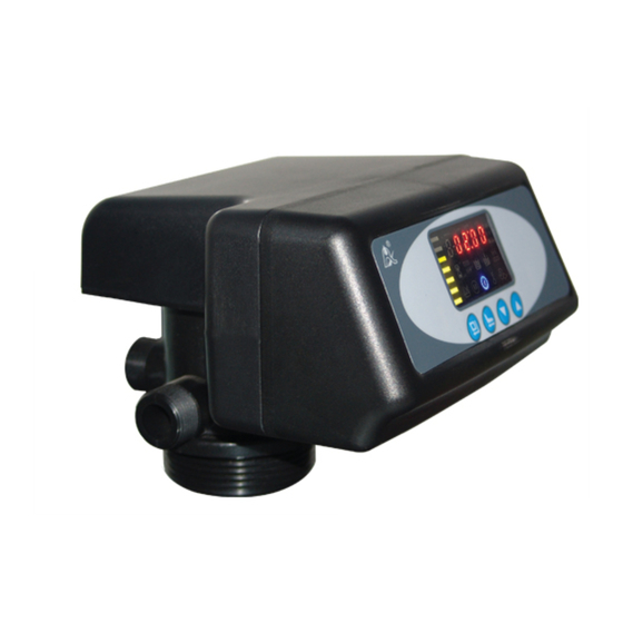
Multi-functional Flow Control Valve for
Please read this manual in details before using the valve
and keep it properly in order to consult in the future.
Water Treatment Systems
53502(Old Model No.: F71B1)
53502B(Old Model No.:F71G1)
53504(Old Model No.:F67C1)
53504B(Old Model No.:F67G1)
53510(Old Model No.:N75A1)
53510B(Old Model No.:N75B1)
User Manual
China Patent No.: ZL02220153.X,
ZL02257746.7
0WRX.466.508
Advertisement

Related Manuals for Runxin N75A1


Summarization of Contents
Product Overview
1.1. Main Application and Applicability
Details the valve's uses and suitability for various water treatment systems.
1.2. Product Characteristics
Outlines key features like sealing, manual function, outage indicator, display, and lock.
Installation
A. Installation Notice
General instructions and precautions before installing the valve.
B. Device Location
Guidance on selecting an optimal and safe placement for the valve unit.
C. Pipeline Connection
Detailed steps for connecting inlet, outlet, and drain pipelines to the valve.
Pipeline Connection Details
Further instructions for pipeline connections, including specific valves and holders.
Drain Pipeline Installation
Instructions for correctly connecting the drain pipeline to the system.
Basic Setting & Usage
2.1. Function of PC Board
Explains the indicators and buttons on the valve's control panel for operation.
2.2. Parameter Specification
Lists parameters, their factory defaults, ranges, and instructions for setting.
Process Display Modes
Illustrates how the control panel displays different working statuses like Service, Backwash, and Fast Rinse.
Applications
3.1. Filter Flow Chart
Visual representation of the water flow path through the filter during its operational cycles.
3.2. Function and Connection of PC Board
Describes the main functions and connection ports of the control board and its components.
Signal Output Connector
Details wiring for control solenoid valves and inlet/outlet pumps based on output modes.
Interlock Function
Explains how interlock cables connect multiple valves for coordinated operation in treatment systems.
Pressure Relief Output
Describes how to use the pressure relief output to prevent damage from rapid pressure changes.
Remote Handling Connector
Covers connecting external devices like TDS meters or PLCs for remote control and monitoring.
System Configuration and Flow Rate Curve
A. Product Configuration
Table showing tank sizes and filter material volumes for carbon and sand filters.
B. Flow Rate Characteristic
Pressure-flow rate curves illustrating valve performance at different flow rates for various models.
Parameter Enquiry and Setting
3.4.1. Parameter Enquiry
Steps to view current parameter settings on the control panel.
3.4.2. Parameter Setting
Procedure to enter program set mode and adjust parameter values.
Parameter Setting Steps
Detailed step-by-step guide for setting Time of Day, Rinsing Time, Frequency, Service Days, and Backwash Time.
Trial Running
Trial Running Procedure
Step-by-step guide for performing initial operation and testing after installation.
Trouble-Shooting
Control Valve Faults
Common problems with the control valve, their causes, and corrective actions.
Controller Faults
Issues related to the control board, display, and electrical service, with solutions.
Error Code Flash
Explanation of error codes (E1, E2, E3, E4) and their corresponding troubleshooting steps.
Assembly & Parts
F71B (53502) Valve Body Assembly
Exploded view and part list for the F71B model valve body.
F71G (53502B) Valve Body Assembly
Exploded view and part list for the F71G model valve body.
F67C (53504) Valve Body Assembly
Exploded view and part list for the F67C model valve body.
F67G (53504B) Valve Body Assembly
Exploded view and part list for the F67G model valve body.
N75A (53510) Valve Body Assembly
Exploded view and part list for the N75A model valve body.
N75B (53510B) Valve Body Assembly
Exploded view and part list for the N75B model valve body.
Warranty Card
Warranty Terms and Conditions
Details the conditions under which the product is not eligible for free repair.
Need help?
Do you have a question about the N75A1 and is the answer not in the manual?
Questions and answers