Table of Contents
Advertisement
Quick Links
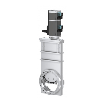
UHV gate valve
with 3 position pneumatic actuator
This manual is valid for the valve ordering numbers:
10836- . E28/48
10840- . E28/48
10844- . E28/48
10846- . E28/48
The respective product identification is given on each valve in the following or in a
similar way:
made in Switzerland
96
Fabrication No.:
patented
F10 – . . . . . / . .
108 . . – . . . . – . . . .
Explanation of symbols:
Read declaration carefully before you start any other
action!
Attention!
Product is in conformity with EC guidelines,
if applicable!
Disconnect electrical power and compressed air
lines. Do not touch parts under voltage!
Read these «Installation, Operating & Maintenance Instructions» and the enclosed «General
Safety Instructions» carefully before you start any other action!
VAT Vakuumventile AG, CH-9469 Haag, Switzerland
Tel +41 81 771 61 61 Fax +41 81 771 48 30 CH@vatvalve.com www.vatvalve.com
Installation, Operating, and Maintenance Instructions
ISO 9001
EN 29001
Series 10.8, DN 63 - 200 (2½" - 8")
Keep body parts and objects away from the valve
opening!
Hot surfaces; do not touch!
Loaded springs and/or air cushions are potential
hazards!
Wear gloves!
278737EB
2003-04-14
1/14
Advertisement
Table of Contents

Related Manuals for VAT 10844 E28/48 Series


Summarization of Contents
Safety Symbols and Instructions
Symbol Explanations
Explains various safety symbols used in the manual.
General Reading Instruction
Instructs to read Installation and Safety Instructions before use.
Imprint Information
Company Details and Copyright
Provides manufacturer, publisher, editor, print details, and copyright notice.
Product Overview and Specifications
Intended Use and Installation
Defines product application and installation advice.
Technical Data and Forces
Covers pressure, temperature, electrical data, and admissible forces.
Connections and Wiring
Compressed Air Connection
Instructions for connecting compressed air supply.
Electrical Connection and Solenoid Wiring
Details electrical hookup and solenoid wiring diagrams.
Valve Operation
Normal and Emergency Operation
Describes normal, compressed air failure, and power failure operation modes.
Intermediate Position Adjustment
Adjustment Procedure
Guides on setting the intermediate position with and without solenoids.
Maintenance and Replacement
Preventive Maintenance and Assembly Replacement
Covers preventive steps and actuator/mechanism assembly replacement.
Position Indicator Kit and Troubleshooting
Indicator Kit and Problem Solving
Details on position indicator kits and common troubleshooting steps.
Support and Warranty
Repairs and Warranty Policy
Information on repair services and product warranty terms.
Need help?
Do you have a question about the 10844 E28/48 Series and is the answer not in the manual?
Questions and answers