Advertisement
Quick Links
21904-3FR-03
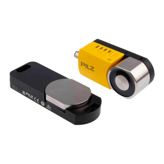
PSEN sl-0.5p
PSEN sl-0.5p
21904-3FR-03
Sicheres Schutztürsystem PSENslock
Das sichere Schutztürsystem erfüllt die Anfor-
1153871755
derungen nach
EN 60204-1
EN 60947-5-3: PDF-M zusammen mit dem
Betätiger (siehe Technische Daten).
EN 62061: SIL CL 3
EN ISO 13849-1. PL e und Kat. 4
Der Sicherheitsschalter darf nur mit dem zu-
gehörigen Betätiger verwendet werden (sie-
he Technische Daten).
Die Sicherheitsausgänge müssen 2-kanalig
weiterverarbeitet werden.
Zu Ihrer Sicherheit
Installieren und nehmen Sie das Gerät nur
547263243
dann in Betrieb, wenn Sie diese Betriebsan-
leitung gelesen und verstanden haben und
Sie mit den geltenden Vorschriften über Ar-
beitssicherheit und Unfallverhütung vertraut
sind.
Beachten Sie die VDE- sowie die örtlichen
Vorschriften, insbesondere hinsichtlich
Schutzmaßnahmen
Durch Öffnen des Gehäuses oder eigen-
mächtige Umbauten erlischt jegliche Ge-
währleistung.
Entfernen Sie die Schutzkappe erst unmittel-
777809547
bar vor Anschluss des Geräts.
1007068171
Wichtig!
Die Magnetoberfläche und die Gegenplatte
können sich erwärmen. Achten Sie bei der
Montage darauf, dass die Wärmeabfuhr ge-
währleistet ist.
Gerätemerkmale
Transpondertechnik
1013887115
Gerätevarianten:
1153877387
– PSEN sl-0.5p 1.1: codiert
– PSEN sl-0.5p 2.1: vollcodiert
– PSEN sl-0.5p 2.2: unikat codiert
1013941387
Zweikanaliger Betrieb
2 Sicherheitsausgänge
2 Eingänge für Reihenschaltung
1 Meldeausgang
Magnetische Zuhaltung für Prozessschutz
1 Eingang zum Ein-/Ausschalten des Zuhal-
temagnets
LED-Anzeige für
– Versorgungsspannung/Fehler
– Tür geschlossen
– Zustand Eingänge
– Zustand magnetische Zuhaltung
8-poliger M12-Anschlussstecker
PSENslock safety gate system
The safety gate system meets the requirements
in accordance with
EN 60204-1
EN 60947-5-3: PDF-M in conjunction with
the actuator (see Technical Details).
EN 62061: SIL CL 3
EN ISO 13849-1. PL e and Cat. 4
The safety switch may only be used with the
corresponding actuator (see Technical De-
tails).
The safety outputs must use 2-channel
processing.
For your safety
Only install and commission the unit if you
have read and understood these operating
instructions and are familiar with the applica-
ble regulations for health and safety at work
and accident prevention.
Ensure VDE and local regulations are met,
especially those relating to safety.
Any guarantee is rendered invalid if the hous-
ing is opened or unauthorised modifications
are carried out.
Do not remove the protective cap until you
are just about to connect the unit.
Notice!
The magnet surface and counterplate may
heat up. When installing, make sure that
heat dissipation is guaranteed.
Unit features
Transponder technology
Unit types:
– PSEN sl-0.5p 1.1: Coded
– PSEN sl-0.5p 2.1: Fully coded
– PSEN sl-0.5p 2.2: Uniquely coded
Dual-channel operation
2 safety outputs
2 inputs for series connection
1 signal output
Magnetic guard locking for process protec-
tion
1 input to switch the locking magnet on/off
LEDs for
– Supply voltage/fault
– Gate closed
– Status of the inputs
– Status of the magnetic guard locking de-
vice
8-pin M12 connector
- 1 -
Système de sécurité pour protecteurs
mobiles PSENslock
Le système de sécurité pour protecteurs mobi-
les satisfait aux exigences des normes
EN 60204-1
EN 60947-5-3 : PDF-M avec l'actionneur
(voir les caractéristiques techniques).
EN 62061 : SIL CL 3
EN ISO 13849-1. PL e et cat. 4
Le capteur de sécurité doit être utilisé uni-
quement avec l'actionneur correspondant
(voir les caractéristiques techniques).
Les sorties de sécurité doivent être traitées par
2 canaux.
Pour votre sécurité
Vous n'installerez l'appareil et ne le mettrez
en service qu'après avoir lu et compris le
présent manuel d'utilisation et vous être fa-
miliarisé avec les prescriptions en vigueur
sur la sécurité du travail et la prévention des
accidents.
Respectez les normes locales ou VDE, parti-
culièrement en ce qui concerne la sécurité.
L'ouverture de l'appareil ou sa modification
annule automatiquement la garantie.
Veuillez retirer le cache de protection avant
de raccorder l'appareil.
Important !
La surface magnétique et la contreplaque
peuvent chauffer. Pour le montage, faites at-
tention à ce que l'évacuation de la chaleur
soit assurée.
Caractéristiques de l'appareil
Technique à transpondeur
Modèles d'appareils :
– PSEN sl-0.5p 1.1 : codé
– PSEN sl-0.5p 2.1 : codé multiple
– PSEN sl-0.5p 2.2 : codé unique
Commande par 2 canaux
2 sorties de sécurité
2 entrées pour montage en série
1 sortie de signalisation
Interverrouillage magnétique pour protéger
les process
1 entrée pour l'activation / la désactivation
de l'aimant d'interverrouillage
LED de visualisation pour
– tension d'alimentation / défauts
– protecteur mobile fermé
– état des entrées
– état de l'interverrouillage magnétique
connecteur M12 à 8 broches
Advertisement

Related Manuals for Pilz PSEN sl-0.5p Series


Summarization of Contents
PSENslock Safety Gate System
For Your Safety
Safety instructions and precautions for installation and use.
Unit Features
Overview of the system's technical features and components.
Function Description
Magnetic Guard Locking and Monitoring
Details on magnetic locking and its monitoring mechanism.
Installation and Wiring
Lateral and Vertical Offset
Diagram and explanation of lateral and vertical offset allowances.
Wiring and Connections
Information on electrical connections, cable length, and pin assignment.
Connection to Evaluation Devices
Safety Output Processing
Critical safety warning about 2-channel processing of safety outputs.
Connection Types and Notes
Description of single connection and notes on AC versions.
Series Connection
Series Connection Warning
Warning about increased delay in series connections of multiple units.
Connecting to Pilz Evaluation Units
PNOZ X, PNOZpower, PNOZsigma, PNOZelog Connections
Connection schemes for various PNOZ evaluation units.
Connection to PNOZmulti and PSS
PNOZmulti Connection Details
Connection details for PNOZmulti with PSENslock.
PSS Connection Details
Connection details for PSS with PSENslock.
Actuator Teaching and Installation
Actuator Teaching Procedures
Instructions for teaching actuators for PSEN sl-0.5p 1.1, 2.1, and 2.2 models.
Important Teaching Notes
Important note that no further actuators can be taught after the first one for model 2.2.
General Installation Guidelines
General instructions for installing the safety gate system and environmental precautions.
Installation at Swing Gate
Swing Gate Mounting Steps
Step-by-step guide for mounting the system on a swing gate.
Installation at Sliding Gate and Adjustment
Sliding Gate Mounting Steps
Step-by-step guide for mounting the system on a sliding gate.
Operating Distance Adjustment
Information on operating distances and offset adjustments.
Operation and Status Indicators
Operational Precautions
Warning about contaminated surfaces affecting electromagnet force and ensuring cleanliness.
Status and Fault Indicators
Explanation of status LEDs and guide to interpreting fault indicators and error codes.
Dimensions and Mounting Brackets
Component Dimensions
Physical dimensions of the safety switch, magnet, actuator, and mounting brackets.
Technical Specifications
Electrical and Timing Data
Detailed electrical specifications and timing parameters of the device.
Environmental and Mechanical Data
Environmental operating conditions and mechanical properties like holding force.
Mechanical and Safety Data
Safety Distances and Actuator Compatibility
Specified safety distances and list of compatible actuators.
Connection and Safety Characteristics
Details on connection type and safety-related characteristic data (PL, SIL).
Ordering Information and Compliance
Product Ordering Data
List of available product types, their features, and order numbers.
EC Declaration of Conformity
Information regarding the EC Declaration of Conformity for the product.
Need help?
Do you have a question about the PSEN sl-0.5p Series and is the answer not in the manual?
Questions and answers