Table of Contents
Advertisement
Advertisement
Table of Contents

Related Manuals for INOR IPAQ C330X


Summarization of Contents
Safety Instructions
1.1 Intended Use
Describes the product's purpose and application in industrial environments.
1.2 Certifications
Lists EU directive compliance and Ex approvals for the device.
1.3 Safety Instructions from the Manufacturer
Covers copyright, disclaimer, liability, and documentation information.
1.3.5 Warnings and Symbols Used
Explains the meaning of various safety symbols and warnings.
1.4 Safety Instructions for the Operator
Provides essential safety guidance for operating personnel.
Device Description
2.1 General Description
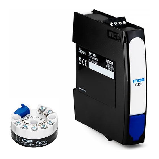
Provides an overview of the IPAQ 330 signal conditioner.
2.2 Nameplate
Details information found on the device's nameplate for identification.
2.3 Scope of Delivery
Outlines what is included with the transmitter and its documentation.
Installation
3.1 In-Head Transmitter
Instructions for installing the in-head transmitter type.
3.2 Rail Mounting Kit for In-Head Transmitters
Details the use of the rail mounting kit for in-head units.
3.3 Rail-Mount Transmitter
Instructions for installing the rail-mount transmitter type.
Electrical Connections
4.1 Safety Instructions
Essential safety precautions for electrical connections.
4.2 Electrical Connections of In-Head Transmitter
Illustrates how to connect the in-head transmitter.
4.3 Connection Diagram of In-Head Transmitter
Shows wiring diagrams for the in-head transmitter.
4.4 Connection Diagram of In-Head Transmitter (Intrinsically Safe)
Wiring diagram for intrinsically safe in-head versions.
4.5 Electrical Connections of Rail-Mount Transmitter
Illustrates how to connect the rail-mount transmitter.
4.6 Connection Diagram of Rail-Mount Transmitter
Shows wiring diagrams for the rail-mount transmitter.
4.7 Connection Diagram of Rail-Mount Transmitter (Intrinsically Safe)
Wiring diagram for intrinsically safe rail-mount versions.
Operation
5.1 NFC Configuration and Logging
Explains NFC configuration and data logging via smartphone.
5.2 Factory Settings for Configuration
Lists default configuration parameters.
5.3 Configuration with ConSoft
Guide for configuring the transmitter using PC software.
5.4 Diagnostic Information according to NAMUR NE 107
Details diagnostic messages and error corrections.
5.5 Factory Default Settings
Specifies the default factory configuration values.
5.6 Sensor Error Monitoring
Describes how sensor faults are indicated.
5.7 System or Sensor Error Correction
Procedures for correcting system or sensor errors.
Service
6.1 Accessory Parts
Lists available accessory parts and their order codes.
6.2 Spare Parts Availability
Information on the availability of spare parts.
6.3 Availability of Services
Details services like repair, maintenance, and support.
6.4 Returning the Device to the Manufacturer
Procedures for returning devices for service.
6.5 Disposal
Guidelines for proper disposal of the device and packaging.
6.5.2 Disassembling and Recycling
Instructions for disassembling and recycling the device.
6.5.3 Disassembling and Recycling of IPAQ C330/C330X
Details material composition for recycling.
6.5.4 Disassembling and Recycling of IPAQ R330/R330X
Details material composition for recycling.
6.5.5 Packaging of IPAQ C330/C330X and R330/R330X
Describes product packaging.
Technical Data
7.1 Measuring Principles
Explains the underlying principles of operation.
7.1.1 Resistance Temperature Sensor
Details the working of resistance temperature sensors.
7.1.2 Thermocouples
Explains the principles of thermocouple operation.
7.2 Technical Data
General technical specifications and features.
7.3 Dimensions
Provides physical dimensions for different transmitter types.
7.4 Temperature Data for Areas with Potentially Explosive Atmospheres
Temperature limits for hazardous areas.
7.5 Output Load Diagram
Visual representation of output load versus power supply.
7.6 Electrical Data for Outputs and Inputs
Detailed electrical specifications.
7.7 RTD and T/C Accuracy Table
Accuracy specifications for RTD and Thermocouple inputs.
Appendix
8.1 Installation and Control Drawings
Lists part numbers and corresponding control drawing numbers.
Specific Conditions of Use
Critical safety conditions for using transmitters in hazardous areas.
Need help?
Do you have a question about the IPAQ C330X and is the answer not in the manual?
Questions and answers