Table of Contents
Advertisement
Advertisement
Table of Contents

Summarization of Contents
Safety Instructions
Intended Use
Defines the IPAQ 330 signal conditioner's purpose and applications.
Certifications
Lists EU directives, ATEX, IECEx, USA, and Canada approvals for the device.
Safety Instructions from the Manufacturer
Covers copyright, disclaimer, product liability, warranty, and documentation information.
Safety Instructions for the Operator
Provides essential safety guidelines for operating personnel.
Device Description
General Description
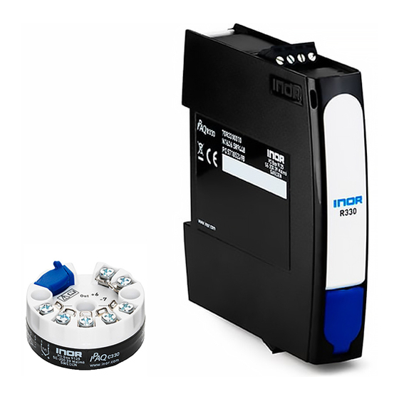
Overview of the IPAQ 330 signal conditioner and its configuration options.
Nameplate
Details the information found on the device's nameplates for identification.
Scope of Delivery
Outlines what is included in the product's delivery package.
Installation
In-Head Transmitter Installation
Instructions for installing the IPAQ 330 in-head transmitter.
Rail Mounting Kit for In-Head Transmitters
Describes the kit and procedure for mounting in-head transmitters on a rail.
Rail-Mount Transmitter Installation
Instructions for installing the IPAQ 330 rail-mount transmitter.
Electrical Connections
Safety Instructions
Crucial safety precautions for performing electrical connections.
Electrical Connections of In-Head Transmitter
Illustrates the input and output signal connections for in-head transmitters.
Connection Diagram of In-Head Transmitter
Provides detailed connection diagrams for the in-head transmitter.
Connection Diagram of In-Head Transmitter (Intrinsically Safe)
Shows connection diagrams for intrinsically safe in-head transmitter versions.
Electrical Connections of Rail-Mount Transmitter
Illustrates the input and output signal connections for rail-mount transmitters.
Connection Diagram of Rail-Mount Transmitter
Provides detailed connection diagrams for the rail-mount transmitter.
Connection Diagram of Rail-Mount Transmitter (Intrinsically Safe)
Shows connection diagrams for intrinsically safe rail-mount transmitter versions.
Operation
NFC Configuration and Logging
Explains how to configure and log data using NFC and a smartphone app.
Factory Settings for Configuration
Details the default factory settings for device configuration.
Configuration with ConSoft
Guide to configuring the transmitter using the ConSoft PC software.
Diagnostic Information according to NAMUR NE 107
Describes diagnostic information and error messages based on NAMUR NE 107.
Factory Default Settings
Lists the default factory settings for the transmitter.
Sensor Error Monitoring
Explains how sensor break or short circuits are indicated.
System or Sensor Error Correction
Procedures for correcting system or sensor errors.
Service
Accessory Parts
Lists available accessory parts and their order codes.
Spare Parts Availability
Information on the availability of spare parts.
Availability of Services
Details the range of services offered by the manufacturer.
Returning the Device to the Manufacturer
Instructions and precautions for returning a device to the manufacturer.
Disposal
Guidelines for the proper disposal of the transmitter and packaging.
Technical Data
Measuring Principles
Explains the underlying principles of resistance temperature sensors and thermocouples.
Technical Data
Provides comprehensive technical specifications and features of the transmitters.
Dimensions
Detailed physical dimensions for both in-head and rail-mount transmitters.
Temperature Data for Areas with Potentially Explosive Atmospheres
Specifies ambient temperature limits for intrinsically safe transmitters in hazardous areas.
Output Load Diagram
Illustrates the maximum permissible output load based on power supply voltage.
Electrical Data for Outputs and Inputs
Detailed electrical specifications for transmitter inputs and outputs.
RTD and T/C Accuracy Table
Table showing accuracy specifications for RTD and Thermocouple inputs.
Appendix
Installation and Control Drawings
References installation and control drawings for IPAQ models.


Need help?
Do you have a question about the IPAQ R330 Series and is the answer not in the manual?
Questions and answers