
Related Manuals for JUKI RF04AS


Summary of Contents for JUKI RF04AS
- Page 1 Electric Tape Feeder RF04AS/RF08AS/RF12AS/ RF16AS/RF24AS/RF32AS/ RF44AS/RF56AS/RF72AS/ RF88AS MAINTENANCE GUIDE...
- Page 2 (3) This manual is prepared with extreme care. However, if you have any question or find any error or omission in writing, contact our dealer or JUKI Corporation. (4) JUKI Corporation shall disclaim all the responsibility for any trouble resulting...
- Page 3 For the safe operation of machinery CAUTION All personnel engaged in the operation of the mounter and its accessories (here after referred to as "machines") including the operators, service and maintenance personnel are required to read through this safety warning to make familiar with its handling to prevent accidents and injuries.
- Page 4 CAUTION Regarding the repair or maintenance (excluding daily inspection and other matters specified in the Manual), ask our company or its agent to do it. General maintenance, inspection, and repair (matters specified in this Manual) shall be conducted only by specialized maintenance engineers who have finished the maintenance course specified by our company.
- Page 5 CAUTION Use Environment To ensure safety, use the machine under the following environment: Environment requirements during operation Temperature : 10℃ to 35℃ Humidity : 30% to 80%RH (No condensation) Altitude : 1,000m or less (Refer to the Operating Instructions published by the manufacturer of the IC for performance assurance of the IC itself.) To prevent accidents due to breakdown of electric/electronic parts, turn on power supply sufficiently after the fear of dew condensation is eliminated, because such condensation may occur when the...
-
Page 6: Table Of Contents
2. Replacing the Splice Sensor (RF08AS/RF12AS/RF16AS/RF32AS/RF44AS/RF56AS/RF72AS) ... 3 3. Replace of Slide Rail .................. 5 3.1. RF04AS / RF08AS / RF12AS / RF16AS / RF24AS ..........5 3.2. RF32AS / RF44AS / RF56AS ................6 3.3. RF72AS / RF88AS ....................7 4. - Page 7 Maintenance Guide 12. Detaching the base plate (RF72AS / RF88AS) ........37...
-
Page 8: Replacing The Operation Panel
1. Replacing the Operation Panel The following describes how to replace the operation panel (membrane switch). Loosen the screws to remove the PCB cover and disconnect the CN8. (Assembly screw tightening torque: 0.29N·m) For RF04AS RF08AS COVER_CS_SCREW_MEC_M26X6 (40167279) RF04AS RF08AS: 40167280 RF12-24AS: 40167279 RF32-88AS: SL4860891SC Remove the rear cable cover (press-fit). - Page 9 Maintenance Guide Remove Reinforced plate, peel off the membrane switch (adhered by the double-sided tape), and then remove the membrane switch. (Assembly screw tightening torque: 0.29N·m) Reinforced plate Adhere the membrane switch to the grip with the double-sided tape, and then perform the wiring and mount the cover in the reverse order of above steps.
-
Page 10: Replacing The Splice Sensor (Rf08As/Rf12As/Rf16As/Rf32As/Rf44As/Rf56As/Rf72As)
Maintenance Guide 2. Replacing the Splice Sensor (RF08AS/RF12AS/RF16AS/RF32AS/RF44AS/RF56AS/RF72AS) Follow the steps below to replace the splice sensor. Mounting the splice sensor Loosen the screws to remove the PCB cover. (Assembly screw tightening torque: 0.29 N·m) For RF08AS COVER_CS_SCREW_MEC_M26X6 (40167279) RF08AS: 40167280 RF12-24AS: 40167279 RF32-72AS: SL4860891SC Disconnect the connector from CN9. - Page 11 Maintenance Guide * In the RF32-72AS, loosen three screws (40167279) to remove the sensor cover. (Assembly screw tightening torque: 0.29 N·m) Sensor cover Sensor Sponge Replace the splice sensor with a new one and mount the PCB cover in the reverse order. Splice sensor * When tightening the self-tapping screws, please tighten along the existing screw threads.
-
Page 12: Replace Of Slide Rail
Maintenance Guide 3. Replace of Slide Rail 3.1. RF04AS / RF08AS / RF12AS / RF16AS / RF24AS Loosen SCREW M2.6 L = 8 (SL4860891SC), remove SLIDE_RAIL (40167213). Replace SLIDE_RAIL, tighten SCREW M2.6 L = 8 (SL4860891SC) while pressing in the direction of the arrow. -
Page 13: Rf32As / Rf44As / Rf56As
Maintenance Guide 3.2. RF32AS / RF44AS / RF56AS Loosen SCREW M2.6 L=8 (SL4860891SC), remove SLIDE_RAIL (40167213). Replace the SLIDE_RAIL, tighten the SCREW M2.6 L = 8 (SL4860891SC) while pressing in the direction of the arrow. (Screw tightening torque: 0.29 N·m) Apply locking agent LOCTITE243 to the male thread. -
Page 14: Rf72As / Rf88As
Maintenance Guide 3.3. RF72AS / RF88AS Loosen SCREW M2.6 L=8 (SL4860891SC), remove SLIDE_RAIL (40167213). SLIDE_RAIL Replace the SLIDE_RAIL, tighten the SCREW M2.6 L = 8 (SL4860891SC) while pressing in the direction of the arrow. (Screw tightening torque: 0.29 N·m) Apply locking agent LOCTITE243 to the male thread. -
Page 15: Replacement Of Reel_Hook
Maintenance Guide 4. Replacement of REEL_HOOK 4.1. RF04AS / RF08AS / RF12AS / RF16AS / RF24AS Loosen SCREW M4X0.7 L = 25 (SM4042501SC), remove REEL_HOOK (40171258) from REEL_HOOK_PLATE (40171257). Replace REEL_HOOK (40171258), through SCREW M4 × 25 (SM4042501SC) in the order shown in the figure below, it is fixed to REEL_HOOK_PLATE (40171257). -
Page 16: Rf32As / Rf44As / Rf56As
Maintenance Guide 4.2. RF32AS / RF44AS / RF56AS Loosen the SCREW M4X0.7 L=25 (SM4042501SC) and NUT (NM6040001SC), remove the REEL_HOOK (40091597). Replace the REEL_HOOK. Then thread the pan head screw M4×25 (SM4042501SC) in the order shown in the figure below and secure the hook with a nut. (Screw tightening torque: 0.54 N·m) REEL_HOOK_32 (40091597) -
Page 17: Replacement Of Upper Cover
For the upper cover exchange of RF08AS, please refer to "RF08AS / RF12AS / RF16AS / RF24AS / RF32AS / RF44AS / RF56AS INSTRUCTION MANUAL". 5.1. RF04AS Loosen SCREW M2.6 L=6 (SM1860601SC). Remove UPPER_PUSHER_BR_08K (40167225), UCSP_R_08K (40167224). (Tool used: Torque driver) SCREW M2.6 L=6... -
Page 18: Rf12As / Rf16As / Rf24As
Maintenance Guide 5.2. RF12AS / RF16AS / RF24AS Loosen COVER_CS_SCREW_MEC_M26X6 (40167279), remove UPPER_PUSHER_BR_08K (40167225) and UCSP_R_12K (40172671). (Tool to use: Torque screwdriver and the bit OHMI-T8) COVER_CS_SCREW_MEC_M26X6 (40167279) UPPER_PUSHER_BR_08K (40167225) UCSP_R_12K (40172671) While pressing Upper cover hook, remove Upper cover. Albania EP-2 is applied to an upper cover contacted part. - Page 19 Maintenance Guide Replace Upper cover, and installed Upper cover in the reverse procedure. (Screw tightening torque: 0.29 N·m) Replace the peel plate, and attach the peel plate in the reverse procedure. (Screw tightening torque: 0.095 to 0.11 N·m) Fit the opening space in the component pick section to the size of components by positioning the peel plate.
-
Page 20: Exchange Of Tensioner Arm
Maintenance Guide 6. Exchange of Tensioner Arm 6.1. RF04AS / RF08AS Loosen SUPER_LOW_HEAD_SCREW_M26X4 (40167277), remove PULL_SENSOR_COVER_A (40167247). (Tool to use: Torque driver and bit OHMI-T6) PULL_SENSOR_COVER_A (40167247) SUPER_LOW_HEAD_SCREW_M26X4 (40167277) · * Screw tightening torque: 0.29 N Remove TENSIONER_SP_08K (40167267) using tweezers. - Page 21 Maintenance Guide Loosen SCREW M3X6 MEC (40052050), remove TENSIONER_ARM_SUB_ASSY_08K (40169541), T_ROLLER_MAIN_SH (40167241), and T_ROLLER (40167240). RF04AS: RF04AS: T_ROLLER_04 (40199021) T_ROLLER_MAIN_SH_rf04 RF08AS: (401241) T_ROLLER (40167240) RF08AS: T_ROLLER_MAIN_SH * When assembling, note the direction. (40167241) (To the side there is a step is the shaft side)
-
Page 22: Rf12As / Rf16As / Rf24As
Maintenance Guide 6.2. RF12AS / RF16AS / RF24AS Loosen SUPER_LOW_HEAD_SCREW_M26X4 (40167277), and remove PULL_SENSOR_COVER_A (40167247). (Tool to use: Torque screwdriver and the bit OHMI-T6) SUPER_LOW_HEAD_SCREW_M26X4 (40167277) · Screw tightening torque: 0.29 N PULL_SENSOR_COVER_A (40167247) Use the tweezers and remove the TENSIONER_SP_12K (40172655). TENSIONER_SP_12K (40172655) * When assembled, applying the Albania EP-2 to the hook portion. - Page 23 Maintenance Guide Loosen SCREW M3X6 MEC (40052050), remove TENSIONER_ARM_SUB_ASSY, T_ROLLER, and the T_ROLLER_MAIN_SH. SCREW M3X6 MEC (40052050) * Gluing material has been applied. (3M: Scotch-Grip 2510) At the time of assembled, whether applying the equivalent product or replaced the screws. (Assembly screw tightening torque: 0.54 N·m) RF12AS : TENSIONER_ARM_SUB_ASSY_12K (40175354) RF16AS : TENSIONER_ARM_SUB_ASSY_16K (40175366)
-
Page 24: Rf32As / Rf44As / Rf56As
Maintenance Guide 6.3. RF32AS / RF44AS / RF56AS Use the tweezers and remove the TENSIONER_SP_12K (40172655). TENSIONER_SP_12K (40172655) * When assembled, applying the Albania EP-2 to the hook portion. Loosen the SCREW M3X6 MEC (40052050), remove the TENSIONER_ARM_ASSY, T_ROLLER, and the T_ROLLER_MAIN_SH. RF32AS : TENSIONER_ARM_SUB_ASSY_32 (40191053) RF44AS : TENSIONER_ARM_SUB_ASSY_44 (40191067) RF56AS : TENSIONER_ARM_SUB_ASSY_56 (40191081) -
Page 25: Exchange Of Chamber Lid
Maintenance Guide 7. Exchange of Chamber Lid 7.1. RF04AS Chamber lid replacement is not necessary to remove the body cover. CHAMBER_LID (40167252) 7.2. RF08AS Loosen COVER_CS_SCREW_MEC_M26X6 (40167279) 2 points, COVER_SC_TAPPING_SCREW_M26X6 (40167280) 9 points, and remove the HANDLE_R_08K (40167257). (Tool to use: Torque screwdriver and the bit OHMI-T8) COVER_CS_SCREW_MEC_M26X6 (40167279)×9... - Page 26 Maintenance Guide Replace CHAMBER_LID (40167252) while opening, assembled in reverse order at the time of disassembly. * When tightening the self-tapping screws, please tighten along the existing screw threads. CHAMBER_LID (40167252) Applying the Albania EP-2 There are 2 kinds of CHAMBER_LID of RF08AS. (Old type · New type) There is no change of part number.
-
Page 27: Rf12As / Rf16As / Rf24As
Maintenance Guide 7.3. RF12AS / RF16AS / RF24AS Loosen COVER_CS_SCREW_MEC_M26, and remove the HANDLE_R. (Tool to use: Torque screwdriver and the bit OHMI-T8) RF12AS : HANDLE_R_12K (40172659) RF16AS : HANDLE_R_16K (40172663) RF24AS : HANDLE_R_24K (40172664) RF12AS : COVER_CS_SCREW_MEC_M26X6 (40167279)×11 RF16AS : COVER_CS_SCREW_MEC_M26X10 (40167668) ×11 RF24AS :... -
Page 28: Rf32As / Rf44As / Rf56As
Maintenance Guide 7.4. RF32AS / RF44AS / RF56AS Loosen the Screw M3x6 MEC (40052050), and remove the BASE_PLATE (40189101). CHAMBER_LID BASE_PLATE (40189101) Loosen the SFBS-M3_L6 (40202970), and remove the CHAMBER_LID. SFBS-M3_L6 (40202970) (Assembly screw tightening torque: 0.54 N·m) WASHER (WP0330816SF) CHAMBER_LID CHAMBER_SH RF32AS : 40189154... -
Page 29: Rf72As / Rf88As
Maintenance Guide 7.5. RF72AS / RF88AS Insert an L wrench (φ3 or less) into the CHAMBER_SH hole to prevent rotation, and remove the two screws SFBS-M3_L6_MEC (40202970). Then remove the CHAMBER_LID, CHAMBER_SH, and the COLLAR. CHAMBER_LID RF72AS :40230186 SFBS-M3_L6_MEC (40202970) RF88AS :40230210 (Assembly screw tightening torque: 0.54 N·m) -
Page 30: Replacing The Wire
Maintenance Guide 8. Replacing the Wire Remove the E-RING2.5 (RE0250000K0) using a slotted precision screwdriver, etc. and unhook the wire end from the CLAMP_BLOCK (40167215). Remove the CLAMP_WIRE_GUIDE_A (40167249) and the CLAMP_WIRE_GUIDE_B (40167250) (at two locations). (Bit T8) CLAMP_WIRE_GUIDE_B(40167250) CLAMP_WIRE_GUIDE_A(40167249) Loosen the CLAMP_LEVER_PIN (40167237) and the screw SFBS-M3_L6_MEC (40202970) to remove the CLAMP_LEVER_SUB_ASSY_R08 (40204901). - Page 31 Maintenance Guide Remove the CLAMP_SPRING_GUIDE (40167238) from the wire. CLAMP_SPRING_GUIDE(40167238) Replace the wire and attach the CLAMP_SPRING_GUIDE (40167238). (At this time, note the position of the washer and the orientation of the CLAMP_SPRING_GUIDE.) CLAMP_SPRING_GUIDE(40167238) Store the spring and the CLAMP_SPRING_GUIDE (40167238) in the CLAMP_LEVER_SUB_ASSY_R08 (40204901).
- Page 32 Maintenance Guide Attach the CLAMP_WIRE_GUIDE_A (40167249) and the CLAMP_WIRE_GUIDE_B (40167250) (at two locations). (Assembly screw tightening torque: 0.29Nm, bit T8) Be careful to pass through the inside of the handle. Pass the wire end through the CLAMP_BLOCK (40167215) and attach the E-RING2.5 (RE0250000K0) using pliers or other tool.
-
Page 33: Removing Foreign Objects That Have Entered The Feeder
Maintenance Guide 9. Removing Foreign Objects That Have Entered the Feeder Loosen the screws to remove the FEED_COVER. (Tool to be used: Torque screwdriver, bit OHMI-T6 / T8) If foreign objects, such as chip components enter the feed gear, remove them with tweezers. * The feed gear is held by the cover through SPROCKET_THRUST_SP_08K (40167264). - Page 34 Maintenance Guide Loosen the screws to remove the PULL_COVER. (Tool to be used: Torque screwdriver, bit OHMI-T6 / T8) If foreign objects, such as chip components enter the pull gear, remove them with tweezers. SUPER_LOW_HEAD_M2.6×4 (40167277) (Assembly screw tightening torque: 0.29 N·m) PULL_GEAR_COVER_12K(40167261) Figure RF04-24AS LOW_HEAD_SCREW_M2.6×4 (40189110)
-
Page 35: Circuit Diagram
Maintenance Guide 10. Circuit Diagram 10.1. RF04AS / RF08AS PWB assembly 40178885 ETF MAIN PCB ASM_C 40178886 ETF PP SENS PCB ASM_C Motor assembly 40166937 MOTOR_ASSY_08K 40204639 MOTOR_ASSY_RF08CD Cannot be exchanged in the field. -
Page 36: Rf12As / Rf16As / Rf24As
Maintenance Guide 10.2. RF12AS / RF16AS / RF24AS PWB assembly 40195307 RF 12 MAIN PCB ASM_C 40178886 ETF PP SENS PCB ASM_C Motor assembly 40166950 MOTOR_ASSY_12K Cannot be exchanged in the field. -
Page 37: Rf32As / Rf44As / Rf56As
Maintenance Guide 10.3. RF32AS / RF44AS / RF56AS PWB assembly 40195307 RF 12 MAIN PCB ASM_C 40178886 ETF PP SENS PCB ASM_C Motor assembly 40166951 MOTOR_ASSY_32K Cannot be exchanged in the field. -
Page 38: Rf72As / Rf88As
Maintenance Guide 10.4. RF72AS / RF88AS PWB assembly 40166952 ETF12 MAIN PCB ASM 40178886 ETF PP SENS PCB ASM_C Motor assembly 40166951 MOTOR_ASSY_32K Cannot be exchanged in the field. -
Page 39: Feeder Setup Stand For Electric Feeder (Rf)
Maintenance Guide 11.Feeder Setup Stand for Electric Feeder (RF) 11.1. Outside View RF work base assembly Reel holder Power switch and power cord Base plate assembly 11.2. Replacing the Power Unit To prevent any trouble caused by accidental machine start, DANGER always shut-down the power before starting the maintenance and adjustment work. - Page 40 Maintenance Guide 3. Remove the washer assembled round head screws M4 L=8 (SL4040891SC) ×4 to detach the power supply from the power unit base. 4. Disconnect the terminals of each unit and replace the POWER SUPPLY (HX005500000). CIRCUIT PROTECTOR×4: HA005240000 RELAY×2: 40174263 POWER SUPPLY: HX005500000 POWER_LAMP_ASM: 40090049...
-
Page 41: Exchange Of Circuit Protector
Maintenance Guide 11.3. Exchange of circuit protector Remove the terminal that is connected from the exchange to CIRCUIT PROTECTOR (HA005240000). Remove the terminals CIRCUIT PROTECTOR (HA005240000) Pinch the circuit protector rear left and right hooks, pushes outward from RF_POWER_UNIT_BASE (40174424). The circuit protector has been replaced in the reverse order of when you remove the attachment, to connect the terminal. -
Page 42: Replacement Of Feeder Power Cable1 Asm (40174255)
Maintenance Guide 11.5. Replacement of FEEDER POWER CABLE1 ASM (40174255) Remove the connector of FEEDER POWER CABLE1 ASM (40174255), and the wiring fixed. Loosen SCREW M3 L = 6 (SL6030692TN) and Connector fixing screw (HK079190000), remove FEEDER POWER CABLE1 ASM (40174255). Connector fixing screw (HK079190000) SCREW M3 L=6 (SL6030692TN) -
Page 43: Circuit Diagram Of Feeder Setup Stand For Electric Feeder (Rf)
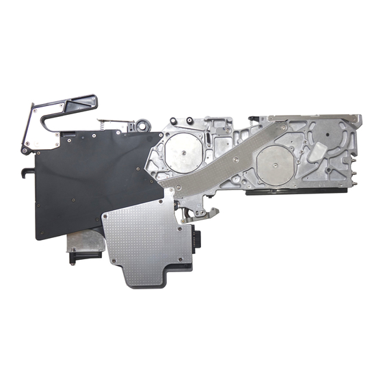
Maintenance Guide 11.6. Circuit Diagram of Feeder Setup Stand for Electric Feeder (RF) - Page 44 Maintenance Guide 12. Detaching the base plate (RF72AS / RF88AS) When detaching the base plate during maintenance of RF72AS or RF88AS, detach and mount it according to the following procedures. Base plate Remove the rear guard. Four screws (40202970) Rear guard Screw ×4 (40202970) Remove the fixing screw (40052050) on the frame side of the idler arm.
- Page 45 Maintenance Guide Remove the screws (40052050 and 40202970) fixing the base plate and detach the base plate. However, do not loosen the following screws. • Hexalobular screw part (Star-shaped hole) • Sub-locate block part • Shim fixing part • Screw on the base plate side of the idler arm (To be remove in the next work) * Remove the screws fixed to the hexagon spacer while holding the hexagon spacer with a hexagon spanner.
- Page 46 Maintenance Guide After maintenance work, mount the base plate. Pass the idler arm shaft through the idler arm and idler springs (left and right). Pay attention to the directions of the spring and the shaft. Pass the slot so that it is at the bottom of the figure.
- Page 47 Remarks Jul. 2016 First edition Aug. 2017 Completely revised Support of RF32AS, RF44AS, and RF56AS Revised Nov. 2017 Completely revised Support of RF04AS Revised Sep. 2018 10. Circuit Diagram Change of Parts No. Revised Nov. 2019 Completely revised Support of RF72AS, RF88AS Revised Oct.
- Page 48 MANUFACTURER INQUIRY SMT TRAINING CENTER 2-11-1, Tsurumaki, Tama-shi, Tokyo 206-8551, JAPAN PHONE: 81-42-357-2295 https://www.juki.co.jp/ Copyright © 2016-2022 JUKI CORPORATION The specification and appearance may be changed without notice. All rights reserved throughout the world. 2022.08 Printed in Japan...
Need help?
Do you have a question about the RF04AS and is the answer not in the manual?
Questions and answers