
Related Manuals for Hill-Rom 305 Manual Bed


Summarization of Contents
Chapter 1: Introduction
Purpose
Manual provides instructions for operation and maintenance of the Basic Care™ Bed.
Audience
Manual is intended for use by facility-approved persons only.
Reference Documents
Refers to the Basic Care™ Bed, 305 Manual Bed, 405 Electric Bed User Manual.
Document Symbols
Explains typefaces and symbols used to improve readability and convey information.
Specifications
Details physical, electrical, and environmental specifications for the bed.
Physical Description
Provides a table of physical dimensions and features of the bed.
Electrical Description
Outlines electrical specifications for Model A and Model B beds and battery specs.
Regulations, Standards, and Codes
Lists relevant technical, quality assurance, and safety standards for the bed.
Model Identification
Identifies product numbers and corresponding bed models and configurations.
Safety Tips
Provides essential safety precautions for operating and servicing the bed.
Warning and Caution Labels
Illustrates and explains various warning and caution labels found on the bed.
Chapter 2: Troubleshooting Procedures
Getting Started
Outlines the initial steps and warnings for troubleshooting bed issues.
Initial Actions
Guides users on gathering initial data from operators to identify potential causes of bed problems.
Function Checks
Details step-by-step checks to isolate and identify operational problems with bed functions.
Final Actions
Describes the concluding steps after function checks to ensure repairs are effective.
None of the Bed Functions Operate
Provides a troubleshooting guide for when no bed functions are operational.
The Head Up Function Does Not Operate
Offers troubleshooting steps for when the head section does not rise.
The Head Down Function Does Not Operate
Provides troubleshooting steps for when the head section does not lower.
The Head Function Does Not Operate
Troubleshooting steps for when the head section control is unresponsive.
The Knee Up Function Does Not Operate
Troubleshooting steps for when the knee section does not raise.
The Knee Down Function Does Not Operate
Troubleshooting steps for when the knee section does not lower.
The Knee Function Does Not Operate
Troubleshooting steps for when the knee function is unresponsive.
The Hilow Up Function Does Not Operate
Troubleshooting steps for when the bed does not raise or lower.
The Hilow Down Function Does Not Operate
Troubleshooting steps for when the bed does not lower.
The Hilow Function Does Not Operate
Troubleshooting steps for when the hilow function is unresponsive.
The Automatic Contour Up Function Does Not Operate
Troubleshooting steps for when the automatic contour up function fails.
The Automatic Contour Down Function Does Not Operate
Troubleshooting steps for when the automatic contour down function fails.
The Trendelenburg or Reverse Trendelenburg Function Does Not Operate
Troubleshooting steps for when Trendelenburg functions are not working.
The CPR Function Does Not Operate
Troubleshooting steps for when the CPR function is unresponsive.
Chapter 3: Theory of Operation
Introduction
Introduces the components and controls of the bed discussed in this chapter.
Base
Describes the function of the bed's base, including casters and brake/steer assembly.
Intermediate Frame
Explains the role of the intermediate frame connecting base to sleep deck and mounting motors.
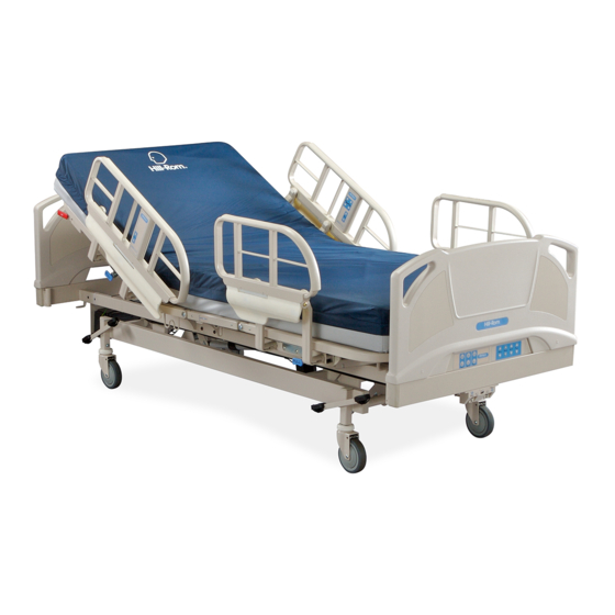
Articulating Sleep Deck
Details the articulating head, seat, knee, and foot sections of the sleep deck.
Siderails
Describes the presence and function of the bed's siderails.
Motion Control
Explains the motion control system for electric and manual beds.
Transformer Configurations
Details transformer configurations for various input voltages on the control board.
Motor Assemblies
Explains motor assemblies and their thermal regulators for overload protection.
Battery Backup
Describes the battery backup system and its operation for CPR and Trendelenburg functions.
Controls
Explains low voltage controls, manual adjustments, and lockout features.
Chapter 4: Removal, Replacement, and Adjustment Procedures
Tool and Supply Requirements
Lists necessary tools and supplies for servicing the bed.
Control Box Assembly
Details procedures for removing and replacing the control box assembly.
Control Panel, Foot End
Provides instructions for removing and replacing the foot end control panel.
Trendelenburg Control Box
Outlines the removal and replacement procedure for the Trendelenburg control box.
Trendelenburg or Reverse Trendelenburg Assembly
Describes the removal and replacement process for Trendelenburg assemblies.
Trendelenburg and Reverse Trendelenburg Indicators
Explains how to replace or reset Trendelenburg indicator caps.
Fuses
Details the procedure for removing and replacing fuses in the control box.
Battery Backup
Provides instructions for removing and replacing the battery backup system.
Head Motor
Outlines the removal, replacement, and adjustment procedures for the head motor.
CPR Cable
Details the removal, replacement, and adjustment procedures for the CPR cable.
Knee Motor
Provides instructions for removing and replacing the knee motor.
Hilow Motor
Outlines the removal, replacement, and adjustment procedures for the hilow motor.
Manual Crank Handle Assembly
Details the removal and replacement of the manual crank handle assembly.
Head or Knee Crank Rod and Drive Screw Assembly (Manual Model Only)
Procedures for removing and replacing crank rod and drive screw assemblies.
Hilow Crank Rod and Drive Screw Assembly Including Gas Springs (Manual Model Only)
Instructions for removing and replacing hilow crank rod/drive screw assembly with gas springs.
CPR Handle Assembly
Details the removal and replacement procedures for the CPR handle assembly.
Siderails
Outlines the process for removing and replacing siderails on the bed.
Siderail Slide Bracket
Procedures for removing and replacing the siderail slide bracket.
Siderail Retraction Assembly
Details the removal and replacement of the siderail retraction assembly.
Siderail Guard Assembly (Foot End)
Instructions for removing and replacing the foot end siderail guard assembly.
Siderail Guard Assembly (Head End)
Instructions for removing and replacing the head end siderail guard assembly.
Siderail Control Assembly
Outlines procedures for removing and replacing the siderail control assembly.
Siderail Control Cable
Details the removal and replacement procedures for the siderail control cable.
Siderail Top Cane
Procedures for removing and replacing the siderail top cane.
Siderail Wire Cover
Details the removal and replacement of the siderail wire cover.
Central Brake and Steer—Caster Assemblies
Procedures for removing and replacing central brake and steer caster assemblies.
Central Brake and Steer—Pedal Assemblies
Outlines removal and replacement procedures for central brake and steer pedal assemblies.
Casters for Individual Brake and Steer
Details the removal and replacement of individual brake and steer casters.
4-Corner Brake and Steer—Caster Assembly
Procedures for removing and replacing 4-corner brake and steer caster assemblies.
Bumper
Instructions for removing and replacing the bed bumper.
Sleep Surface Panels
Procedures for removing and replacing various sleep surface panels.
Chapter 5: Parts List
Service Parts Ordering
Provides instructions on how to identify and order replacement parts using part numbers.
Exchange Policy
Outlines the policies for in-warranty and out-of-warranty parts exchanges.
Warranty
Details the limited warranty terms for the Basic Care™ Bed(s).
Recommended Spare Parts
Lists recommended spare parts for servicing Model A and Model B beds.
Base Frame—Model A
Illustrated parts list for the base frame of Model A beds.
Upper Frame—P1440—Model A
Illustrated parts list for the P1440 upper frame of Model A beds.
Upper Frame—P1441—Model A
Illustrated parts list for the P1441 upper frame of Model A beds.
Siderails—Model A
Illustrated parts list for siderails of Model A beds.
Power Cord
Illustrates various power cord types for the bed.
Sleep Surface
Illustrated parts list for the sleep surface components.
Base Frame—Model B
Illustrated parts list for the base frame of Model B beds.
Upper Frame—P1440—Model B
Illustrated parts list for the P1440 upper frame of Model B beds.
Siderails—Model B
Illustrated parts list for siderails of Model B beds.
Chapter 6: General Procedures
Cleaning and Care
Provides essential warnings and guidelines for cleaning and caring for the bed.
General Cleaning
Instructions for cleaning the bed unit with a dampened cloth and disinfectants.
Steam Cleaning
Advises against steam cleaning due to potential damage from moisture.
Hard to Clean Spots
Offers methods for removing difficult spots and stains from the bed.
Disinfecting
Guidelines for diluting disinfectants and germicides as per manufacturer labels.
Component Handling
Safety precautions for handling PC boards and electronic components.
PC Board
Advises caution when servicing PC boards to prevent damage or malfunctions.
Lubrication Requirements
Details lubrication requirements, including specific lubricants for bearings and gears.
Preventive Maintenance
Emphasizes the importance of regular maintenance for bed longevity and performance.
Preventive Maintenance Schedule
Provides a schedule outlining functions and procedures for routine preventive maintenance.
Preventive Maintenance Checklist
A checklist to track preventive maintenance tasks, costs, and inspections.
Sleep Mode
Procedure to conserve battery power when the bed is disconnected from AC power.
CPR Cable Adjustment
Instructions for adjusting the CPR cable to ensure proper head section lowering speed.
Chapter 7: Accessories
Accessories
Lists available accessories for the Hill-Rom® Basic Care™ Bed.
IV Pole—P1445
Instructions for installing, removing, and adjusting the IV pole accessory.
Trapeze Support—P846F
Details the installation and removal procedures for the trapeze support accessory.
Fracture Frame Adapter—P847B and P847C
Instructions for installing and removing fracture frame adapters for specific socket sizes.
Need help?
Do you have a question about the 305 Manual Bed and is the answer not in the manual?
Questions and answers