
Related Manuals for MTU 12V2000M41B


Summarization of Contents
1 Safety
1.1 Important provisions for all products
General information on product safety, nameplates, and emission regulations.
1.2 Personnel and organizational requirements
Guidelines for personnel involved in operation, maintenance, and repair, including PPE.
1.3 Transportation
Instructions for transporting engines with and without flange-mounted gearboxes.
1.4 Safety regulations for maintenance and repair work
Safety measures for preparing, performing, and after maintenance or repair tasks.
1.5 Fire prevention and environmental protection, fluids and lubricants, indirect materials
Safety guidelines for fire prevention, noise, disposal, and handling of materials.
1.6 Standards for safety notices in the text
Explanation of DANGER, WARNING, CAUTION, and NOTICE symbols used in the manual.
2 General Information
2.1 Engine side and cylinder designations
Defines engine sides (A/B) and cylinder numbering conventions.
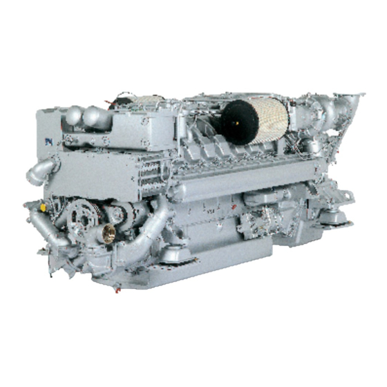
2.2 Product description
Overview of the engine's components: engine, fuel system, exhaust, turbocharging, cooling, service block, and electronic system.
2.3 Series 2000 M40A/B - M41A/B
Overview of functional groups and engine model designation key.
2.4 Sensors and actuators – Overview
Diagrams showing sensors and actuators on the engine's overhead view.
2.5 Sensors and actuators – Overview
Diagrams showing sensors and actuators on the top view of a 12V 2000 M engine.
3 Technical Data
3.1 8V 2000 M40A engine data: engine-mounted heat exchanger, reference conditions: 25 °C intake air temperature
Technical specifications for 8V 2000 M40A engine with engine-mounted heat exchanger.
3.2 8V 2000 M40A engine data: separate heat exchanger, reference conditions: 25 °C intake air temperature
Technical specifications for 8V 2000 M40A engine with separate heat exchanger.
3.3 8V 2000 M40B engine data, engine-mounted heat exchanger, reference condition: 25 °C intake air temperature
Technical specifications for 8V 2000 M40B engine with engine-mounted heat exchanger.
3.4 8V 2000 M40B engine data, separate heat exchanger, reference condition: 25 °C intake air temperature
Technical specifications for 8V 2000 M40B engine with separate heat exchanger.
3.5 8V 2000M41A engine data: Engine-mounted heat exchanger
Technical specifications for 8V 2000M41A engine with engine-mounted heat exchanger.
3.6 8V 2000M41A engine data: Remote heat exchanger
Technical specifications for 8V 2000M41A engine with remote heat exchanger.
3.7 8V 2000M41B engine data: Engine-mounted heat exchanger
Technical specifications for 8V 2000M41B engine with engine-mounted heat exchanger.
3.8 8V 2000M41B engine data: Remote heat exchanger
Technical specifications for 8V 2000M41B engine with remote heat exchanger.
3.9 12V 2000 M40A engine data: Engine-mounted heat exchanger, reference conditions: 45 °C intake air temperature
Technical data for 12V 2000 M40A engine with engine-mounted heat exchanger at 45°C.
3.10 12V 2000 M40A engine data: Engine-mounted heat exchanger, reference conditions: 25 °C intake air temperature
Technical data for 12V 2000 M40A engine with engine-mounted heat exchanger at 25°C.
3.11 12V 2000 M40A engine data: Separate heat exchanger, reference conditions: 25 °C intake air temperature
Technical data for 12V 2000 M40A engine with separate heat exchanger at 25°C.
3.12 12V 2000 M40A engine data: Separate heat exchanger, reference conditions: 45 °C intake air temperature
Technical data for 12V 2000 M40A engine with separate heat exchanger at 45°C.
3.13 16V 2000 M40A engine data: engine-mounted heat exchanger, reference conditions: 25 °C intake air temperature
Technical data for 16V 2000 M40A engine with engine-mounted heat exchanger at 25°C.
3.14 16V 2000 M40A engine data: engine-mounted heat exchanger, reference conditions: 45 °C intake air temperature
Technical data for 16V 2000 M40A engine with engine-mounted heat exchanger at 45°C.
3.15 16V 2000 M40A engine data: separate heat exchanger, reference conditions: 25 °C intake air temperature
Technical data for 16V 2000 M40A engine with separate heat exchanger at 25°C.
3.16 16V 2000 M40A engine data: separate heat exchanger, reference conditions: 45 °C intake air temperature
Technical data for 16V 2000 M40A engine with separate heat exchanger at 45°C.
3.17 16V 2000 M40B engine data, engine-mounted heat exchanger, reference condition: 45 °C intake air temperature
Technical data for 16V 2000 M40B engine with engine-mounted heat exchanger at 45°C.
3.18 16V 2000 M40B engine data, engine-mounted heat exchanger, reference condition: 25 °C intake air temperature
Technical data for 16V 2000 M40B engine with engine-mounted heat exchanger at 25°C.
3.19 16V 2000 M40B engine data, separate heat exchanger, reference condition: 25 °C intake air temperature
Technical data for 16V 2000 M40B engine with separate heat exchanger at 25°C.
3.20 16V 2000 M40B engine data, separate heat exchanger, reference condition: 45 °C intake air temperature
Technical data for 16V 2000 M40B engine with separate heat exchanger at 45°C.
3.21 ENGINE DATA 12V 2000M41A/B
Engine data for 12V 2000M41A/B models, covering various configurations.
3.22 ENGINE DATA 16V 2000M41A/B
Engine data for 16V 2000M41A/B models, covering various configurations.
3.23 Firing order
Specifies the firing order for different engine cylinder configurations.
3.24 Engine – Main dimensions
Provides main dimensional data (length, width, height) for various engine models.
4 Operation
4.1 LOP – Control elements
Description and function of control elements on the Local Operating Panel (LOP).
4.2 Putting the engine into operation (out-of-service period > 3 months)
Procedure for restarting an engine after an extended period of disuse.
4.3 Putting the engine into operation after scheduled out-of-service period
Procedure for restarting an engine after a scheduled maintenance period.
4.4 Starting the engine from LOP (without BlueLine automation system)
Steps for starting the engine using the LOP without automation.
4.5 Operational monitoring
Guidelines for monitoring engine performance during operation.
4.6 Stopping the engine at the LOP
Procedure for safely stopping the engine using the LOP.
4.7 Emergency engine stop from LOP
Procedure for performing an emergency engine stop using the LOP.
4.8 After stopping the engine
Steps to take after the engine has been stopped, including draining coolant.
4.9 Plant – Cleaning
Instructions for cleaning the plant using high-pressure cleaning units.
5 Maintenance
5.1 Maintenance task reference table [QL1]
Table referencing maintenance tasks and their corresponding page numbers.
6 Troubleshooting
6.1 ECU alarms
Explanation of ECU alarms and their meanings.
6.2 Troubleshooting
Guides for diagnosing and resolving common engine issues.
6.3 LOP fault messages
List of fault messages displayed on the LOP and their corresponding measures.
7 Task Description
7.1 SOLAS
Information and procedures related to SOLAS shielding.
7.2 Engine
Tasks related to the engine, including barring and cranking.
7.3 Cylinder Liner
Procedures for inspecting and examining cylinder liners.
7.4 Crankcase Breather
Maintenance procedures for the crankcase breather system.
7.5 Valve Drive
Procedures for checking and adjusting valve clearance.
7.6 Injection Pump / HP Pump
Procedures for replacing and installing the injection pump.
7.7 Injection Valve / Injector
Procedures for replacing and installing injectors.
7.8 Fuel System
Tasks related to the fuel system, including HP fuel lines and venting.
7.9 Fuel Filter
Procedures for replacing and maintaining fuel filters.
7.10 Charge-Air Cooling
Checking the intercooler condensate drain line.
7.11 Air Filter
Procedures for replacing and installing the air filter.
7.12 Air Intake
Checking the signal ring position of the service indicator.
7.13 Starting Equipment
Procedure for checking the starter condition.
7.14 Lube Oil System, Lube Oil Circuit
Procedures for checking and changing engine oil.
7.15 Oil Filtration / Cooling
Procedures for marking the oil dipstick and replacing the oil filter.
7.16 Coolant Circuit, General, High-Temperature Circuit
Procedures for draining and filling engine coolant.
7.17 Raw Water Pump with Connections
Procedure for checking the relief bore on the raw water pump.
7.18 Belt Drive
Procedure for checking the condition of the drive belt.
7.19 Battery-Charging Generator
Procedures for checking and adjusting the battery-charging generator drive belt.
7.20 Engine Mounting / Support
Procedure for checking the condition of engine mounting resilient mounts.
7.21 Wiring (General) for Engine/Gearbox/Unit
Procedure for checking engine cabling.
7.22 Accessories for (Electronic) Engine Governor / Control System
Procedures for cleaning engine control unit and EMU components.
7.23 Emergency Instrumentation (Local Operating Panel)
Procedures for cleaning LOP and its connectors.
8 Appendix A
8.1 Abbreviations
List of abbreviations used in the manual.
8.2 MTU Contact/Service Partners
Contact information for MTU support and service partners.
9 Appendix B
9.1 Special Tools
List of special tools required for various maintenance tasks.
Need help?
Do you have a question about the 12V2000M41B and is the answer not in the manual?
Questions and answers