Advertisement
t110/t130 – Marine Satellite Television System
INSTALLING THE ANTENNA
10
System Package
Antenna Unit
ACU (Antenna Control Unit)
Installation Kit
Planning the Installation
Selection of Antenna Installation Site
System Cables
Power Requirement
Tools Required for Installation
Antenna Installation
Unpacking the Wooden Crate
Remove Antenna Shipping Restraints
Antenna Dimensions
Antenna Mounting Templates
Preparing Antenna Supporting Pole
Mounting the Radome
Installing the System Cables
RF Cable Connections
Advertisement
Table of Contents

Summarization of Contents
System Package
Antenna Unit
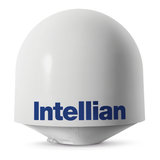
The antenna unit includes an antenna pedestal inside a radome assembly unit.
ACU (Antenna Control Unit)
The Antenna Control Unit (ACU) provides power to the antenna and controls various settings of the antenna.
Installation Kit
Contains the items required for securing the antenna unit and ACU to your vessel.
Planning the Installation
Selection of Antenna Installation Site
Install the antenna for maximum performance with a clear view of the horizon or satellite all around.
Tools Required for Installation
Lists the necessary tools for installation, such as spanners, drill, and screwdrivers.
System Cables
Points to consider before installing system cables, including clamping and protection.
Power Requirement
The Intellian t110/t130 is designed to work on a vessel's power supply rated at 110-220 V AC.
Antenna Installation
Unpacking the Wooden Crate
Remove the four shipping bolts which mount the antenna to the pallet for unpacking.
Remove Antenna Shipping Restraints
Open the radome's hatch and remove shipping restraints, then check antenna movement.
Antenna Dimensions
Confirm the height and diameter of the antenna before installing it for a secure installation.
Antenna Mounting Templates
Provides mounting patterns for t110 and t130 models, showing dimensions for installation.
Preparing Antenna Supporting Pole
Details recommended dimensions for the support pedestal and base panel for the antenna.
Mounting the Radome
Bolt the Radome base directly to the support pedestal using the supplied bolts.
Installing the System Cables
Insert coax cables through strain relief, route them, and seal deck penetrations securely.
RF Cable Connections
Connect RF cables to the antenna control unit and power switch box using an 11mm spanner.


Need help?
Do you have a question about the T110 and is the answer not in the manual?
Questions and answers