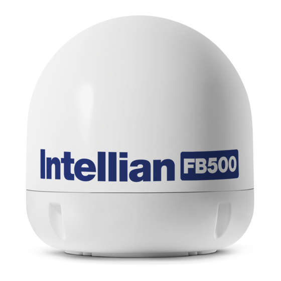
Page 1
FB250/FB500 Installation and Operation User Guide Global Leader in Marine Satellite Antenna Systems...
Page 2
Information in this document is subject to change without notice. Every effort has been made to ensure that the information in this manual is accurate. Intellian is not responsible for printing or clerical errors. Doc. No. 2014FB-UM1222-V2_3...
LIST OF CONTENT REGULATORY INFORMATION INTRODUCTION Introduction Overview of the Fleetbroadband Main units INSTALLATION Installation Connections GETTING STARTED Getting started Using the primary handset Using the web console Using the network management TROUBLESHOOTING TECHNICAL SPECIFICATION WARRANTY...
FCC CAUTION: Any Changes or modifications not expressly approved by the manufacturer could void the user's authority, which is granted by FCC, to operate this satellite Fleet- Broadband System FB250 / FB500.
EC Declaration of Conformity: Intellian Technologies, Inc., 348-5 Chungho-ri, Jinwi-myeon, Pyeongtaek-Si, Gyeonggi-do, Korea 451- 862 declares under our sole responsibility that the accessory Product, brand name as Intellian and models: FB250 / FB500 FleetBroadband satellite communication system, to which this...
INTRODUCTION Introduction Overview of the Fleetbroadband Main units...
Page 8
FB250/500 User Manual 1. INTRODUCTION The Intellian FB250 / FB500 User Equipment is a dedicated compact solution specifically designed to meet the FleetBroadband ( FBB ) services for the maritime environment providing seamless ocean coverage from 76° North to 76° South.
Page 9
• I/O Port • GPS Output Port The number of RJ45 Ethernet ports and RJ11 ports for the BDUs of the FB250 and FB500 is illustrated below: RJ45 Ethernet Ports for PC and router 4 LAN Ports (including 2 PoE)
Page 10
FB250/500 User Manual 2. OVERVIEW OF THE FLEETBROADBAND BGAN Services The Broadband Global Area Network (BGAN) is a global Satellite Internet Network using portable terminals. The terminals are usually connected to a laptop comput- er to access broadband Internet in remote locations, where a line-of-sight to the satellite exists.
Page 11
3. MAIN UNITS The FB250/500 FleetBroadband system include the following main units: FB250 • FB250 FleetBroadband BDU • FB250 FleetBroadband ADU • Primary Handset FB500 • FB500 FleetBroadband BDU • FB500 FleetBroadband ADU • Primary Handset 3.1 Above Deck Unit (ADU), the antenna unit The FB series ADU is Maritime FleetBroadband 3-axis controlled antenna.
Page 12
FB250/500 User Manual 3.2 Below Deck Unit (BDU) The BDU has been developed for maximum flexibility and is the controlling unit for the FBB UE. It features a reliable industry standard interfacing field and enables users to have optimal connectivity no matter what the conditions or your position at sea.
Page 13
Status LEDs There are 3 Status LEDs to indicate the operational status of the BDU at one glance. Each LED is assigned to the following function: • BDU Terminal Status • ADU Status • Registered to Network Status SIM Card Slot The BDU has a SIM (Subscriber Identity Module) card slot located at the connec- tor panel behind a small cover plate.
Page 14
FB250/500 User Manual Front panel The following diagram shows the front panel of the BDU. 1. Resettable Circuit Breaker 2. Grounding Stud 3. Power Switch 4. DC Power Connector 5. Antenna (N-Type) Connector 6. SIM Card Slot 7. PoE Ports (RJ45) 8.
Page 15
3.3 Primary Handset The wired Primary Handset has a colour LCD and keypad for making and receiv- ing voice calls and sending SMS using an interface similar with a mobile phone. It can serve as a remote access for user to access various BDU functions. The Primary Handset connector is plugged into the BDU primary handset port and it is powered directly from the BDU.
Page 18
• Spring Washer x 5 (M6) • Flat Washer x 5 (M6) • Nut x 5 (M6) FB250 with Intellian i4 Matching Dome • Hex. Bolt x 5 (M8x35L) • Spring Washer x 5 (M8) • Flat Washer x 5 (M8) FB500 •...
Page 19
4.1 Installation of ADU Planning the Installation Install the antenna in accordance with the following procedures to ensure maxi- mum performance of the antenna. The antenna should be installed in a place where it has an all-around clear view of the horizon. Please be sure there are no obstacles within 15 degrees above the antenna.
Page 20
Radome Dimension of FB250 Radome Dimension of FB250 with Intellian i3 matching dome FB250 Standard with Intellian i2 matching dome Ø50 cm (19.7”) 43cm (16.9”) 70 cm (27.5”) Radome Dimension of FB250 with Radome Dimension of Intellian i4 matching dome FB500 Standard...
Page 21
An exposed cable may cause electric shock and cause serious damage to the equipment. 144.25 Mounting Position of FB250 Standard and Mounting Position of FB250 with FB250 with Intellian i2 Matching Dome Intellian i3 Matching Dome 23.3cm ( 9.2”)
Page 22
Remove the rubber cap from RF connector. Connect the RF cable to the RF connector under the base plate through the access hole. Be careful not to over tighten, as you may damage the connector. FB250 Standard Cable Connection FB250 Cable Connection for Intellian i4 Matching Dome FB500 Standard Cable Connection Note: Do not tighten excessively when using the spanner, this will damage the threads.
FB250 FB500 Note: For FB250 with Intelian i4 system, use the hex head bolts (M8x35L), M8 Spring washers and M8 flat washers supplied. In this case, it is recommended to use a 13mm Spanner. For FB500, apply the Loctite 263 on four M8 Hex Bolts as shown in the picture below before starting the mounting procedures.
Page 24
FB250/500 User Manual 4.2 Installation of BDU The BDU box is unpacked and the following items should be checked whether they are present: • BDU • 1 meter Wired Primary Handset with cradle • 1.5 meters Ethernet Cable • 1.8 meters Telephone Cord •...
Page 25
Ambient Temperature -25°C to +55°C Relative Humidity Up to 95% at +40°C The BDU can be installed on a desktop, bulkhead, top ceiling or under captain’s console. The procedure of the installing the BDU is simple as follow: • Place the BDU on the desired installation area. •...
Page 26
FB250/500 User Manual 4.3 Installation of Primary Handset The primary handset is provided with cradle. It can be mounted on a desktop, bulkhead, top ceiling or under captain’s console as similar as the BDU. The primary handset is to be separated from its cradle so that the cradle can be fixed with the M5 x 12mm self-tapping screws.
Page 27
5. CONNECTIONS Below is the interconnection diagram of FB UE with the cables. Bolt to Primary vessel’s hull Handset 12V/24V DC 3m DC Power Cable Vessel’s power distributor 1m Handset Cable 1.8m Telephone Cable 1.5m Ethernet LAN (Category 5)Cable Computer G3 Fax Machine...
Page 28
FB250/500 User Manual 5.1 BDU’s Outputs Connection The additional information of the output ports of GPS and GPIO. GPS Output RJ11 (Offset) Connector The BDU has a The Transceiver Unit has a GPS output RJ11 (Offset) connector for outputting the GPS data in NMEA0183 format.
Page 29
GPIO Output The BDU has a dedicated circular connector to provide GPIO (General Purpose Input/Output) interface to the external devices. GPIO Output GPIO Port Pin Signal Name Dsecription of Signal Color Code GPIO-1 RES_1 Reserve line 1 Black GPIO-2 Ground line Brown GPIO-3 LED_ENABLE...
Page 30
FB250/500 User Manual Grounding Stud The BDU has a grounding stud with a locking screw for the earth cable (with its colors of green and yellow) with its UE lug. It is recommended to include spring washers to secure the UE lug to the grounding stud.
GETTING STARTED Getting started Using the primary handset Using the web console...
Page 32
FB250/500 User Manual 6. GETTING STARTED 6.1 System Configuration Above Deck Unit (To be installed in an exposed area) Below Deck Unit (To be installed in an protected area) +12V / 24V DC Primary Handset AC/DC Power Non-SOLAS Supply Unit...
Page 33
6.2 Preparation for Operation Install the SIM card. The system requires a SIM card to access the Inmarsat’s FleetBroadband network and configure the settings of the BDU. Please refer to your Airtime Service Provider for more information. 1. Tilt up the SIM card slot rubber cover. Note: Make sure the BDU is switched off before inserting or removing the SIM card.
Page 34
FB250/500 User Manual Connecting Primary Handset The Primary Handset is powered from the BDU through the Primary Handset Port. 1. Plug in the Primary Handset connector into the Handset port on the BDU front panel. Make sure the key of the handset is aligned to the red mark of the handset port.
Page 35
Powering Up the System 1. Use the ON/OFF switch on the BDU’s front panel. 2. Wait for all LED indicators to turn green to indicate the system is com- pletely power up. Refer the table below for meaning of the status indicators. LED Name Status Meaning...
Page 36
FB250/500 User Manual Entering your SIM PIN When you acquire the SIM card from the Airtime Service Provider, a PIN (Personal Identification Number: 4 to 8 digits) is provided together with it. Note: You will need to enter the PIN at start-up if the FBB BDU has been powered down.
Page 37
7. USING THE PRIMARY HANDSET 7.1 The Primary Handset The Primary Handset is connected to the FBB UE using the dedicated HANDSET port and is powered directly from the BDU. Equipped with a large 2’, 65K CSTN, 220 Liquid Crystal Display (LCD), Primary Handset not only acts as a standard phone that allows you to make/ receive voice calls, it also serves as a remote access UE (User Equipment) for you to access various configurations supported by the BDU.
Page 38
FB250/500 User Manual 7.2 Powering Up the Primary Handset The Primary Handset is automatically powered up once it is connected to the dedicated HANDSET port. Depending on the conditions of the BDU, the Primary Handset may start in the following modes:...
Page 39
7.3 Primary Handset 1. Earpiece 2. Display 3. Ear-set Jack 4. OK Key 5. 4-Way Navigation Ring 6. Left Selection Key 7. Right Selection Key 8. Call/Answer Key 9. Call/Menu End Key 10. Keypad (Alpha-numeric) 11. Mode Key 12. Clear Key 13.
Page 40
FB250/500 User Manual Keypad - Description and Functions Keys Description / Functions 4-way navigation ring* Press the 4-way navigation ring to scroll left, right, up, and down on the display. Enables scrolling through names, phone numbers, menus or settings. OK key* Pressing this key selects/confirms the function highlighted on the display.
Page 41
The Main Display Screen FB 500 Contacts Menu 1. BDU Status Indicator line The indicator line shows status symbol informing you about the operating conditions of the BDU. 2. Satellite The indicator line shows status symbol informing you about the satellite service.
Page 42
FB250/500 User Manual Primary Handset Status Indicators Table below explains the meaning of each status indicator displayed in the Main Display screen. Status Indicator Description New short message (SMS) in inbox. Available CS domain services. Available PS domain services. Data connection is inactive. (Available in Manage profiles sub menu only) Data connection is active.
Page 43
Primary Handset Operations Making a Voice Call Before making a voice call, please make sure that: - The Primary Handset is connected to the BDU. Status indicator should be on.) - The Primary Handset is NOT radio silent. ( Status indicator should be off.) - The BDU has successfully registered with the network and ready for CS do- main (voice) services.
Page 44
FB250/500 User Manual Adjusting volume during a call Use the 4-way navigation ring 4-way navigation ring* to adjust the volume. Press ‘up’ key to increase the volume. Press ‘down’ key to decrease the volume. ghl’ pqrs wxyz 中 中 MODE...
Page 45
Using the Menus You can access the Menu System by pressing the Right selection key* in the Main Display screen. The main menu of the Primary Handset includes nine (9) menu options with each menu option having their respective sub-menus. You can use the 4-way navigation 4-way navigation ring* to navigate to the desired menu option and press OK Key* to confirm your selection.
Page 46
FB250/500 User Manual Contacts Menu The Contacts menu allows you to store, retrieve and update names and phone numbers of your contacts in the Primary Handset memory and in the SIM card memory. You can also access this menu by pressing Left selection key* in Main Display screen.
Page 47
Note: Refer to “Tips for writing the text” section under New message for more information on text writing. • Search : Select this to enter a specific name to search within the contact list. • Delete : Delete selected contact. Note: You can also delete the selected contact by pressing the Clear key*.
Page 48
FB250/500 User Manual Log Menu The Log menu allows you to view historical information about phone calls and data usage in chronological order with the following sub menus: Missed calls Received calls Dialled calls Call history of the particular category is displayed in chronological order when selected.
Page 49
Telephony Menu The Telephony menu allows you to configure telephony related settings with the following sub menus: Port Settings • Primary Handset Contain options for incoming and outgoing call types. Select this to configure the call type settings. The following options are available when pressing the Left selection key* while browsing through the list: - Standard...
Page 50
FB250/500 User Manual Speed dial • Setting Contain options to enable/disable the speed dial feature • Speed Dial List Select this to configure the speed dial list. The following options are available when pressing the Left selection key* while browsing through the list: •...
Page 51
Data Menu The Data menu provides the following sub menus to manage and configure data connections (PDP profiles) for the BDU: Manage profiles Allow you to manage the Primary and Secondary PDP profiles. • Primary profiles One Standard Primary PDP profile has been created in the Primary profile list as a default profile.
Page 52
FB250/500 User Manual Adding / Editing profiles You can press the Left selection key* or OK key* from the option list to add new or edit existing profile settings. • Profile name Specify the name of the profile. • Connection type Both Standard and Streaming connection types are supported.
Page 53
Note: For 32k, 64k and 128k Streaming profiles, there are three additional options when selecting editing their settings. The additional options are: • Desired rate Choose the desired rate for the different profiles. Note that the default setting for each profile is the profile chosen. For example, for 32k Streaming, the default rate is 32k.
Page 54
FB250/500 User Manual Note: You will be prompted to save the changed settings before exiting the sub menu. Press Left selection key* or OK key* to save the changes. Icon in the profile list indicates that the profile is not active and icon indicates that the profile is currently active in use.
Page 55
To de-activate a primary data connection when there is an active connection: 1. From the data status list, select Options using the Left selection key*. 2. Select Deactivate using Left selection key* or OK key*. 3. You are prompted to confirm de-activation. Confirm de-activation by selecting Yes using the Left selection key* or OK key*.
Page 56
FB250/500 User Manual Tips for writing the text: • Press the 0 key to add a space. • To quickly change the text input mode when writing text, press Hash key* repeatedly and check the indicator at the top of the display: o <ABC>: Capital letters...
Page 57
The following are available options when pressing the Left selection key* while browsing through or viewing the messages in this folder: • Open Open selected message. You can also press OK key* while browsing through or viewing the messages in this folder: •...
Page 58
FB250/500 User Manual Sent Contain text messages that you have sent. The following are available options when pressing the Left selection key* while browsing through or viewing the messages in this folder: • Open Open selected message. You can also press OK key* while browsing through the message list to open the selected message (This option is not avail able when viewing the message).
Page 59
• Send Send this message to another recipient. Save • Save the selected message into the Draft folder. • Add to contact Select this to add the phone number of the selected message into the contact list. Note: You can also make a voice call to the selected message contact when browsing through the message list by pressing the Call/Answer key*.
Page 60
FB250/500 User Manual Settings Menu The Settings menu provides the following sub menus to configure the BDU: Ciphering mode Contain options to enable/disable the use of ciphering mode between the network and BDU. Note: Status icon is displayed in the Main Display screen when ciphering is enabled.
Page 61
- Lease time Display the lease time. Default lease time is 60. Except for DHCP server, the rest of the display settings can be edited by pressing the Left selection key* or Ok key*s. Note: Make sure that the format is correct when entering an IP address. Press the Star key* multiple times to insert the “.”...
Page 62
FB250/500 User Manual Supplementary Configure settings related to supplementary services. These settings are applica- ble to standard CS voice services. Note: Depending on the network, some settings may not be available or may prevent other settings from being activated. The following information is available: •...
Page 63
Pressing the OK key* configures a particular forwarding condition. The following settings can be configured: Status: Display active or inactive status of the selected forwarding condition. Press the OK key* to change the status. Number: Display number to forward calls to when selected forwarding condition is active.
Page 64
FB250/500 User Manual You can press the Left selection key* for options available when browsing through the list of barring conditions. The list of options is: • Retrieve Retrieve network settings of the highlighted condition. • Retrieve all Retrieve network settings of all the listed conditions.
Page 65
• Call Waiting Contain options to enable/disable call waiting services. You can also press the Left selection key for the following options: • Retrieve Retrieve network settings of the call waiting service. • Update Update configured settings to the network. Note: Always use Retrieve option to retrieve the latest settings from the network.
Page 66
FB250/500 User Manual Terminal Menu The Transceiver menu provides the following sub menus to check for information and perform resets on the BDU: Signal strength Show graphical representation of current signal strength and GPS type. Table below describes the available GPS type icons used in this sub menu: This icon shows that the BDU is in the process of acquiring a GPS fix when there is no previously stored GPS fix.
Page 67
Antenna Unit Info Display a list of information of the Antenna. • Serial number Serial number of the Antenna Transceiver restart Soft restarting the BDU Limited reset Perform limited reset on the BDU. Apart from full factory reset that is not available in Primary Handset, limited reset only resets a small portion of the BDU settings.
Page 68
FB250/500 User Manual Security settings Menu The Security Settings menu provides the following sub menus to configure the security settings of the BDU using different PIN: Terminal PIN SIM PIN There are three options available for selection under each sub menus to manage the PIN and security settings for the BDU: •...
Page 69
Phone manager Menu The Phone manager menu provides the following sub menus to configure settings that are local to the Primary Handset: Display Configure settings that are relatged to Primary Handset display. • Backlight To set the duration of the display backlight to remain on. Settings range from Always On (Backlight permanently turned on), 15 seconds to 1 minute.
Page 70
FB250/500 User Manual • Ring tone - Tone Select desired ring tone pattern. - Volume Configure the volume of the ring tone. Using the 4-way navigation ring*, press up/right to increase and down/left to decrease the volume. Language Allow you to change the menu display language.
Page 71
8. USING THE WEB CONSOLE 8.1 Register to the Network 1. Connect your computer to the FBB BDU using a LAN cable. 2. When the connection has been established, open the web browser. 3. Type http://192.168.1.35 in the Address field and press Enter. 4.
Page 72
FB250/500 User Manual The FBB BDU Web Console will appear on your screen. The FBB BDU will automatically register to the network. This process will include GPS acquisition, satellite tracking and registration with the network, which will take a few minutes.
Page 73
8.2 Navigating the Web Console Menu Overview Below you can see all of the sub menu tabs, under each icon menu item. Setup Phone Data Settings Terminal Info Phonebook Compose Network Management Language Satellite Selection Call History Inbox Connection Terminal Info Sent Primary Profiles Ethernet...
Page 74
FB250/500 User Manual Status Icons Status Indicator Description Indicates the Circuit Switch service status (Voice calls, Circuit Switch Icon SMS, FAX). Indicates the Packet Switch service status Packet Switch Icon (Internet Browsing, FTP, email.) GPS Icon Indicates if a new GPS fix is available or not.
Page 75
8.3 Navigating the Web Console Setup Menu Viewing Terminal Information 1. Click on Setup icon. 2. Click Terminal Info. The terminal information tab shows Signal strength, Temperature, GPS Status, Elevation angle and Registration status. Signal Indicates the received signal strength (C/No in dB Hz). Temperature Indicates the UE’s current operating temperature status.
Page 76
FB250/500 User Manual Satellite Selection The default Satellite Selection is in Auto mode. In Auto mode, the UE will scan all the visible satellites and track the satellite with the most optimum elevation angle or the last used satellite. Note: Changing the satellite selection will terminate any existing active voice/fax call or data connections.
Page 77
Phone Menu 1. Click on Phone icon Phone menu provide the following options: I. PhoneBook • The Phonebook entries can be stored on the SIM card or the FBB BDU. • Allows you to view, add, edit and delete entries on your Phonebook list. •...
Page 78
FB250/500 User Manual Storage Usage Shows the number for Phonebook entries used in the SIM card and TU locations. For example: (SIM –2/150) indicates: Storage location – SIM card Total number of entries used = 2 Total number of entries available = 150 Adding a new Phonebook entry •...
Page 79
Deleting a Phonebook entry • Select the entry from the Phonebook list • Click Delete. • Click Ok to confirm to delete the entry...
Page 80
FB250/500 User Manual Sending SMS from the Phonebook Follow these steps to send SMS from the Phonebook: 1. Select the entry from the Phonebook list. 2. Click Send SMS. 3. The Phonebook console switches over to the Compose SMS console.
Page 81
View option The View option allows you to view the Call History entries. From the drop-down menu, select: To view the list of the dialed, received and missed calls. Dialed Call To view the list of dialed calls only. Received Call To view the list of received calls only.
Page 82
FB250/500 User Manual Deleting a Call History entry Follow these steps to delete a call History entry: 1. Select the entry from the Call History list. 2. Click Delete. 3. Click Ok to confirm or click Cancel to abort deleting the entry.
Page 83
SMS Menu 1. Click on SMS icon. SMS menu provide the following options: I. Compose To compose and send text messages. Simply enter a mobile number, type your message and click Send. II. Inbox Shows the details (Sender information, Message, Date and Time stamp) of all SMS received.
Page 84
FB250/500 User Manual I. Compose Composing a New Message Follow these steps to compose a new SMS: 1. Enter the receiver’s Phone number in the Phone no. field or click the Phone- book icon if the receiver’s number is listed in the Phonebook.
Page 85
II. Inbox Shows the details (Sender information, Message, Date and Time stamp) of all SMS received. Replying to a SMS Follow these steps to reply a SMS: 1. Click on a SMS to select it. The selected SMS will be highlighted in light blue. 2.
Page 86
FB250/500 User Manual Forwarding an SMS Follow these steps to forward an SMS: 1. Click on a SMS to select it. The selected SMS will be highlighted in light blue. 2. Click Forward. The Inbox console switches over to the Compose console.
Page 87
III. Sent Shows the detail (Receiver information, Message, Date and Time stamp)of all SMS sent. Resending a sent SMS Follow these steps to resend a sent SMS (sending the same SMS to the same receiver): 1. Click on a SMS to select it. 2.
Page 88
FB250/500 User Manual Forwarding a sent SMS Follow these steps to forward a sent SMS to another recipient: 1. Click on a SMS to select it. 2. Click Forward. 3. The Sent console switches over to the Compose console. 4. Enter the receiver’s number in the Phone No. field.
Page 89
Deleting multiple SMS from the Sent list Follow these steps to delete multiple SMS from the sent list: 1.Select the message by checking the checkboxes beside each SMS. 2. Click Delete. 3. Click OK to confirm the delete, or Cancel to abort the delete. 4.
Page 90
FB250/500 User Manual Forwarding a draft SMS another recipient Follow these steps to forward a draft SMS to another recipient: 1. Click on a SMS to select it. 2. Click Forward. The Draft console switches over to the Compose console.
Page 91
Deleting multiple SMS from the Draft list Follow these steps to delete multiple SMS from the Draft list: 1. Select the message by checking the checkboxes beside each SMS. 2. Click Delete. 3. Click OK to confirm the delete, or Cancel to abort the delete. 4.
Page 92
FB250/500 User Manual I. Network Management The terminal can support up to 11 different Network User Groups for different types of services with their desired configuration and settings. Each Network User Group has their own profile and settings such as QOS (Standard/Streaming) and...
Page 93
II. Connection 1. To activate the default profile, click Activate Default Profile. The PDP context will be activated. When connected, APN and the assigned public IP Address details will be dis- played. You can proceed to access the Internet and use the related features. 2.
Page 94
FB250/500 User Manual III. Primary Profiles Primary profiles define the connection type. You can select from a list of profiles to be the default primary profile and con- nection type. From Profile 7 to Profile 10, you can create your own customized primary profile.
Page 95
Access Point Name (APN) By default, the APN from the SIM will be selected. Follow these steps to change the Access Point Name (APN): 1. Select User Defined. 2. Enter the new APN in the field space provided (e.g. BGAN inmarsat.com). 3.
Page 96
FB250/500 User Manual Pre-defined Secondary Profiles The following Traffic Flow Template have been pre-defined for the following profiles. - FTP - Quick Link - Quick Time Media - Real Media - Streambox - Win Media User can define settings from Profile 7 to Profile 10. User can also click on Add from Templates to choose pre-defined settings.
Page 97
3.The pre-defined settings of the selected profile will updated on the webconsole. User can either make any further required changes to the settings.
Page 98
FB250/500 User Manual V. Port Forwarding Port Forwarding is a feature for Router (multiple-user) mode. This feature sets the FBB BDU to direct incoming traffic on certain TCP/UDP port to a specific port on a local PC (IP Address). Follow these steps to add a new forwarding rule: 1.
Page 99
VI. Firewall By default, the Firewall is disabled. Enable Firewall Settings 1. Navigate to Data>Firewall>Setup to enable Firewall protection. 2. Select Enable. 3. Click Update.
Page 100
FB250/500 User Manual Incoming Rule To add and define up to 10 rules to allow or reject incoming packets.
Page 101
Outgoing Rule To add and define up to 10 rules to allow or reject outgoing packets.
Page 102
FB250/500 User Manual DoS Protection To protect the terminal and the private network against unnecessary DoS attacks from the untrusted public network by: Block packets with spoofed source IO addresses from public network (protects against LAND attack and others that use reserved/private source IP addresses).
Page 103
Service Filtering To prevent external network accessing the terminal by blocking packets such as Ping, Telnet, access web console and access to AT command service. By default, the Service Filtering is disabled.
Page 104
FB250/500 User Manual Administrator Control To block any keyword in the content of the accessing page. VII. PPPoE By default, the PPPoE is disabled. 1. Select Enable. 2. Click Update. 3. Once the PPPoE service is enabled, a pop-up message box indicates the...
Page 105
VIII. Misc This feature requires the activation of the next PDP to take effect. User has to enable the VPN Passthrough first then activate the PDP context. 1. Select IPSec or PPTP. 2. Click Update. 3. Once the required option is updated, a pop-up message box indicates the the update is successful.
Page 106
FB250/500 User Manual Settings Menu 1. Click on Settings icon. Setting menu provides the following options: I. Language II. Terminal Info III. Ethernet IV. Telephony V. PIN VI. SMS VII. Wi-Fi VIII. Tracking IX. Admin X. Support XI. Accounts XII. About I.
Page 107
II. Terminal Info This tab shows general information about the UE, Error/Event Logos and Call Logs. Information Displays information about the Manufacture ID, Software version, Model ID, IMEI number, IMSI number (only when a SIM card is inserted), Subscriber number and Antenna Unit’s serial number.
Page 108
FB250/500 User Manual Call Log Displays the call history including standard voice calls, high-quality / fax calls, standard data sessions. (By default, Pin is “0000”) User can retrieve choose to delete or export the CS or PS logs in this menu.
Page 109
III. Ethernet 1. Click Ethernet to view and edit the Ethernet settings. 2. Click Update to allow the settings to take effect. DHCP 1. Click DHCP to view and edit the DHCP settings. 2. Click Update to allow the settings to take effect. Mac Address Filtering 1.
Page 110
FB250/500 User Manual Reject List All PCs/Laptops (also applicable for WiFi access) will be allowed to access the BDU except for those (MAC addresses) listed in the Reject List. Allow List All PCs/Laptops (also applicable for WiFi access) will be denied access to the BDU except for those (MAC addresses) listed in the Allow List.
Page 111
Static Route Users can configure the static route to create a new entry route in the router’s rout- ing table. It allows the network to forward packets to the IP address destination stored in the routing table. 1. Click Add to setup new Static Route. 2.
Page 112
FB250/500 User Manual IV. Telephony Interface 1. Select European Caller Line ID Phone connected or US Caller Line ID Phone connected from the Telephone Interface Configuration drop-down menu. 2. Click Update to allow the setting to take effect. Port Configuration For each of the 3 ports, a choice of the quality calls can be selected.
Page 113
Fax Port For the fax port, if no subscription is made, there will be no choices. If fax subscription is made, 3.1 KHz high quality fax call will be available. Caller ID 1. Click Retrieve to get current setting of the Allow called party to see your number configuration.
Page 114
FB250/500 User Manual Call Waiting 1. Click Retrieve to get current setting of the Enable call-waiting configuration. 2. To change the setting, select Yes or No for the Enable call waiting configuration. 3. Click Apply to allow the new setting to take effect.
Page 115
Call forwarding 1. Click any individual Retrieve option to get current setting of the corresponding scenario in which incoming calls would be forwarded. 2. Select the scenario in which the calls should be forwarded, or deselect the sce- nario to disable the corresponding call forwarding setting. 3.
Page 116
FB250/500 User Manual Call Restriction The Call Restriction is only enabled for outgoing call. There are 2 types of restriction: 1. Phonebook - The user is only able to make outgoing calls from the phonebook list. 2. Call List - In this segment, it further categorised into Allowed List and Blocked List for the 3 types of telephony functions.
Page 117
V. PIN Terminal PIN 1. Click Transceiver PIN to configure the Transceiver PIN settings. 2. Select Disabled if you do not need to set the Transceiver PIN. 3. Select Enabled to set the Transceiver PIN. 4. Enter the PIN number in the Enter PIN filed and click Update PIN. Follow these steps to change the Transceiver PIN: 1.
Page 118
FB250/500 User Manual SIM PIN 1. Click SIM PIN to configure the SIM PIN settings. 2. Select Disabled if you do not need to set the SIM PIN. 3. Select Enabled to set the SIM PIN. 4. Enter the PIN number in the space provided and click Update PIN.
Page 119
SIM PIN2 1. Click SIM PIN2 to configure the SIM PIN2 settings. 2. Select Disabled if you do not need to set the SIM PIN2. 3. Select Enabled to set the SIM PIN2. 4. Enter the PIN number in the space provided and click Update PIN. Follow these steps to change the PIN Password: 1.
Page 120
FB250/500 User Manual Remote control Select Allow only listed numbers for secure mode, allowing only authorised mobile numbers to send commands to the BDU. Select ACK SMS remote command to receive SMS acknowledgement from the BDU, after sending a SMS command.
Page 121
VII. Wi-Fi By default, the Wi-Fi is disabled. Select Enabled to turn on the Wi-Fi module. (Go to Wireless Setting to enable Wi-Fi to be accessible by other devices.) Click Update. Once the Wi-Fi service is enabled, a pop-up message box indicates the Wi-Fi service is activated.
Page 122
FB250/500 User Manual Wireless Settings 1. Select Enabled to allow the Wi-Fi network access to Wi-Fi enabled devices. 2. Choose ideal network mode, channel bandwidth and channel. 3. If required, Network Name can be renamed by user. Security Settings Follow the steps to configure the security settings of the Wi-Fi module.
Page 123
VIII. Tracking Settings 1. Select Disabled if you do not need GPS reporting. 2. Select Enabled if you need GPS reporting. 3. Select either IP Data or SMS mode. 4. Key in the desire frequency in seconds. (The time interval to update the server.) 5.
Page 124
FB250/500 User Manual Geo Fence 1.There are two ways to enter latitude/longitude: a) Degrees, minutes, seconds. b) Decimal degrees. 2. Select the desire latitude/longitude format. 3. Click the Add. 4. Select the alarm trigger type: a) In b) Out c) In and Out 5.
Page 125
APN (Access Point Name) This APN is configured to channel the tracking data traffic unlike the APN de- fined under DATA> Primary profile which is used for user data traffic such as Web browsing, FTP, Email etc. By default, the SIM is selected which mean the APN stored in the Sim card will be used for the tracking function.
Page 126
FB250/500 User Manual Firmware Upgrade Firmware upgrade is to update your FBB BDU with the latest firmware. Please refer to your respective distributor for your firmware download. Warning: DO NOT abort the upgrading process or unplug the power of the FBB BDU during the firmware upgrade process at any time.
Page 127
Note: If the FBB BDU web console didn’t appear, you can manually re-fresh the web console by clicking the F5 on your keyboard. 4. Browse to the location of the new firmware, select, and click Upload. 5. Firmware upgrade will take approximately 10 to 12 minutes to complete. 6.
Page 128
FB250/500 User Manual Reboot Terminal If you wish to reboot the FBB BDU, click Reboot Terminal. Click Reboot and wait for a few minutes to allow the TU to reboot. Refresh your browser to update the Web Console page after reboot.
Page 129
GPS Output By default, FBB BDU Transceiver Unit outputs the GPS data in NMEA format (at 9600bps) via the NMEA 0183 Connector for GPS output. For technician who wants to diagnose the system, he/she may collect the debug log messages by se- lecting Output Debug Log.
Page 130
FB250/500 User Manual Remote access By enabling the Remote Access option, user can remotely (from shore) access the terminal’s web console via internet. In order to have a remote access, the termi- nal should be set in Router Mode ( multi-user ) and a PDP context active. If there is no active PDP context, the user can activate the PDP context by means by SMS command.
Page 131
Backup/Restore Data backup and restore refers to the copying and archiving of data so it may be used to restore the device settings after a data loss event. Partial backup option is a time saving method to replicate the same set of setting across different terminals of the same model It is recommended to save the backup data of the terminal in a storage media so that in the event the there is any loss of data on the UT or primary computer, the...
Page 132
FB250/500 User Manual This tab allows user to configure the web access. - HTTP For remote access of web console, the user can configure the port number differ- ent from the default Port number: 80 if user wants to host a web server on the PC attached to the UT.
Page 133
X. Support Display information of the support telephone number, support email address, Sup- port URL and Services URL. (The information shown is for sample purpose only.) XI. Accounts Select Add to add new user. 1. Select Delete to delete specific user. 2.
FB250/500 User Manual 9. USING THE NETWORK MANAGEMENT The network management system enables the system administrator to setup differ- ent user gro ups and manage how each profile is connected to the Inmarsat BGAN network. The UT can support up to 11 different Network User Groups for different types of services with their desir ed configuration and settings.
Page 135
• NAT enabled; DHCP enabled • When there is no active PDP context, PC 1 to PC N get a private IP address each from the DHCP pool (Default range: 192.168.1.40 ~ 192.168.1.59) • After a primary PDP context is activated, the private IP address will remained unchanged.
Page 136
FB250/500 User Manual DMZ Mode DMZ stands for demilitarized zone and it allows full bi-directional communication between one client computer and the Internet. Therefore, if a computer is added to routers DMZ, it will forward all incoming connections to that computer.
Page 137
Network Classification Network Classification identifies which devices or computers are part of which Net- work User Group and its entry classifies how it will register on the Inmarsat BGAN network. The following configurations have to be defined: 1. MAC address 2.
Page 138
FB250/500 User Manual Obtaining MAC Address 1. Open Command Prompt and type ipconfig /all. 2. The MAC address will fall under Ethernet adapter Local Area Connection > Physical Address. 3. Physical Address is the MAC address, where the dash (-) should be replaced with colon (:).
Page 139
Network User Group Network User Group defines the group of computers and devices sharing one common met hod for registration. In addition, it specifies how they are being regis- tered to the Inmarsat BGAN network. It consists of the following parameters: •...
Page 140
FB250/500 User Manual Profile Name: User will not be able to change profile name for Default group. Profile names from Profile 1 to Profile 10 can be changed as required. Status: Select Activate PDP Context for allowing internet access and Deactivate PDP Context to forbid internet access.
Page 141
Traffic Statistics Traffic Statistics screen displays the detailed traffic information of each network user group, which allows the user to monitor the traffic and locate faults promptly. Description of the items in Traffic Statistics The items associated with the Traffic Statistic are defined below: •...
Page 142
FB250/500 User Manual Enabling Traffic Statistics To enable the tracking of traffic statistics, navigate to Data> Network Manage- ment> Network User Group. Select Statistics Report under Status label. Click on Update for the settings to take effect. After enabling the Traffic Statistics in Network User Group page, go to the Traffic...
Page 143
Attached Devices Attached devices display the list of devices that is connected to the UT. Examples of Network Management Configuration Setup The following are examples for setting up the configuration for the following con- nection types. 1. NAT or Shared Mode: The user can access the internet from NAT( Network Address Translation) and sent and receive the packets from NAT.
Page 144
FB250/500 User Manual NAT or Shared Mode Navigate to Network User Group and click on Edit for Default Group as shown the following figure. The following are the configurations to be made: • Profile Name – Default Group • Status – Activate PDP context •...
Page 145
Next, open command prompt and enter the ping 8.8.8.8 –n 1 for sending the one packet. I f you want to send 10 packets, you can write 10 instead of 1, i.e. ping 8.8.8.8. –n 10. You will see successful pinging session with reply. Go to the Traffic Statistics page.
Page 146
FB250/500 User Manual To receive TCP packets, open Internet Explorer and enter any web page URL. i.e. www.yahoo.com...
Page 147
Go to the Traffic Statistics page and click on Refresh. You will observe that other than the increase in duration, Bytes (Tx & Rx), NAT (Tx & Rx), ICMP packets (Tx & Rx), TCP packet (Tx), TCP packets (Rx) and UDP (Tx & Rx) have increased too. Direct Mode Navigate to Network User Group, click Edit in the Default Group row and select the Direct in connection type.
Page 148
FB250/500 User Manual You will see the changes in the following figure. Under the Auto Activation column, the PDP IP address (161.30.23.232) is shown. In direct mode, the packets are sent directly to the internet, which means that there are no interfaces like NAT or firewall. Therefore, there is a need to change the PC’s IP address to the PDP’s IP address.
Page 149
3. Click on Properties. 4. Double click on Internet Protocol Version 4 (TCP/IPv4).
Page 150
FB250/500 User Manual 5. Change the PC’s IP address to the PDP’s IP address. Next, open command prompt and enter ping 8.8.8.8 –n 1. You will see successful pinging session with reply.
Page 151
DMZ mode Navigate to Network User Group, click Edit in the Default Group row and se- lect the DMZ in connection type. Input your computer IP address in the DMZ IP address box. Click on Update for the settings to take effect.
Page 152
FB250/500 User Manual The following figure shows that connection type is updated to DMZ. Next, open command prompt and enter ping 8.8.8.8 –n 1. You will see successfu l pinging session with reply. Navigate to the Traffic Statistics page and click on Refresh. You will notice that the duration, Bytes (Tx &...
Page 153
No Internet mode In No Internet access mode, you will see how it works using two network user groups call ed Default group and No Network group to do the illustration. 2 profiles will be created to demonstrate the differences between Shared mode and No int ernet access mode.
Page 154
FB250/500 User Manual The figure below shows the configuration settings for No_Network Group in No Internet Acc ess mode. Click on the Edit at the second row to create another group called No Network.
Page 155
The following are the configurations to be made: • Profile Name – Default Group • Status – Deactivate PDP context • Connection Mode – No Internet Access Click on Update for the settings to take effect The figure below shows the configuration settings for No_Network Group in No Internet Access mode.
Page 156
FB250/500 User Manual Click Create on the first row to create the Network Classification for Default Group. IP address Range – 192.168.1.40 – 192.168.1.50 i.e. the IP address range that you wish to be active the PDP in shared mode Network User Group –...
Page 157
Click Create on the second row to create the Network Classification for No_Net- work group. IP Address Range – 192.168.1.30 – 192.168.1.34 There is no internet access for PCs with IP addresses within this range as the packets sent from these PCs will be dropped or denied. If the computer in use has an IP address of 192.168.1.30, any packets sent from this computer will be denied or dropped.
Page 158
FB250/500 User Manual Next, open command prompt and enter ping 8.8.8.8 –n 1. You will see unsuccess- ful pinging session with reply. You will notice that the reply is “Destination host unreachable” as the IP address of the computer in use for No-Network user group is 192.168.1.30 (within the pre-set IP address range), it cannot ping to the Internet.
Page 160
FB250/500 User Manual 10 TROUBLESHOOTING General LED status BDU LED LED behavior Descriptions / Remedial Actions BDU is in power-off state. Steady amber BDU is powering up. Steady green BDU successfully powered up. Steady red System failure during boot up or operation. User action required.
Page 161
SIM Card Symptons Descriptions / Remedial Actions • Ensure that a correct Inmarsat SIM card is used. SIM Card • Ensure that a SIM card is properly inserted into SIM Card slot. cannot be detected • Retry by re-inserting the SIM card into SIM Card Slot before powering up the BDU.
Page 162
FB250/500 User Manual RJ11 Phone Port for Standard Call Symptons Descriptions / Remedial Actions • Make sure that there is dial tone before making the call. For the case of busy tone, o Ensurethatthelineisnotengagedbyanyother telephone services. Unable to make o Ensure that all other telephony devices are hung up properly.
Page 163
web Console Symptons Descriptions / Remedial Actions • Ensure that there is no problem with the Ethernet connectivity. Unable to access • Ensure that IP address is entered correctly. Web Console • Try to refresh the browser after correcting the problem. •...
Page 164
FB250/500 User Manual Antenna / Satellite Signal Level Symptons Descriptions / Remedial Actions • Check any obstruction such as the hull or monkey bridge of the vessel that may block the ADU’s line of sight. • Check any interference signal from other electronics devices that are...
FB250/500 User Manual Warranty This product is warranted by Intellian Technologies Inc., to be free from defects in materials and workmanship for a period of Three (3) YEARS on parts and ONE (1) YEAR on labor performed at Intellian Technologies, Inc. service center from the purchased date of the product.
Need help?
Do you have a question about the FB250 and is the answer not in the manual?
Questions and answers