
Related Manuals for Dorma ES 420


Summarization of Contents
Safety and Compliance
General Safety Instructions
Important instructions for safe operation and installation of the door system.
Important Technical Data
Key technical specifications for the ES 410/420 system, including voltage and temperature.
Standards, Laws, and Regulations
Compliance requirements with applicable national and international standards.
Closing Edge Hazards
Identifies pinch, shear, and impact risks at automatic door closing edges.
Special Protection for Vulnerable Persons
Requirements for protecting children, elderly, or disabled users from door hazards.
Recycling and Disposal
Guidelines for environmentally sound disposal of the product and its packaging.
Installation and Commissioning Safety
Safety During Mounting
Securing the work area and handling the unit safely during installation.
Safety During Commissioning
Ensuring proper electrical connections and safety checks before operation.
Inspection and System Approval
Procedures for checking and approving the installed system's functionality.
User Safety and Product Information
Intended Application and Liability
Specifies the product's intended use and limits manufacturer liability.
Safety Instructions for Operation
Key safety rules for operating the automatic door system.
Important Technical Data
Essential technical specifications like voltage, fuse, temperature, and humidity.
Residual Risk and Vulnerable Persons
Addresses remaining risks and specific protective measures for vulnerable users.
Recycling and Disposal
Guidance on the proper disposal of the product and packaging.
Operational and Maintenance Guidelines
Safety During Mounting
Precautions for securing the workspace and handling components during installation.
Briefing the Operator
Essential handover and training procedures for the system operator.
Maintenance and Care Procedures
Instructions for regular upkeep and cleaning of the door system.
Wear Parts Identification
Lists components subject to wear and requiring regular inspection/replacement.
Declaration of Conformity
EC Directives Compliance
Statement of compliance with relevant EU directives for machinery and safety.
Applied Standards and Regulations
Lists the specific harmonized European standards applied for the product.
Technical Data and Door Parameters
Electrical Specifications
Details on supply voltage, fuse rating, and power consumption.
Door Opening and Weight Specifications
Parameters for door opening width and maximum panel weight for ES 410/420.
Operational Settings and Special Functions
Adjustment of speeds, hold-open times, and special operational features.
Installation Preparation
Explanation of Pictograms
Explains symbols used throughout the installation instructions.
Important Notes Before Installation
Crucial guidelines and prerequisites before starting the physical installation.
Mounting Diagrams: Door Panel and Drive Unit
Mounting Plate and Door Panel Dimensions
Illustrations detailing mounting plate and door panel dimensions.
Single-Leaf Door Mounting Examples
Visuals for single-leaf door installation (left and right opening).
Double-Leaf Door Mounting Example
Visual guide for double-leaf door installation.
Door Opening Width Diagrams
ES 410 Single-Leaf Opening Widths
Diagrams showing clear opening width for ES 410 single-leaf doors.
ES 410 Double-Leaf Opening Widths
Diagrams illustrating clear opening width for ES 410 double-leaf doors.
ES 420 Double-Leaf Opening Widths
Diagrams showing clear opening width for ES 420 double-leaf doors.
Installation Steps: Mounting Rail
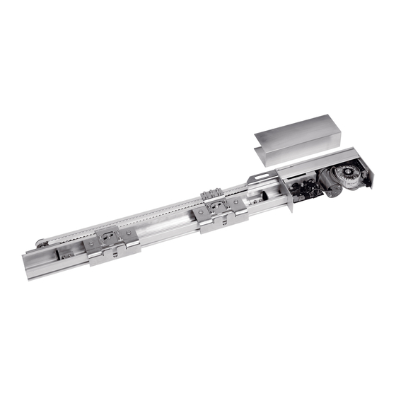
Mounting Rail Installation Detail
Illustration showing the mounting rail and its components.
Attaching the Mounting Rail
Visuals for attaching the mounting rail to the structure.
Door Panel Attachment and Adjustment
Attaching Door Panels to Carriers
Diagrams showing how to attach door panels to the carriers.
Adjusting Door Panel Alignment
Visuals for adjusting the alignment of the door panels.
Cover Installation and Clearance Settings
Adjusting Drive Unit Clearance
Diagram showing adjustment of the drive unit's position.
Cover Installation for Passage Heights
Visuals for installing covers based on passage height.
Checking Door Panel Movement
Checking Left-Opening Door Movement
Visuals to check movement of left-opening door panels.
Checking Right-Opening Door Movement
Visuals to check movement of right-opening door panels.
Checking Double-Leaf Door Movement
Visuals to check movement of double-leaf door panels.
Electrical Connections and Grounding
PE Connection and Grounding
Illustration of the protective earth connection for the system.
Connection Board and Reset Function
Diagram of the connection board and reset button.
Terminal Definitions and Wiring
Terminal Connections Overview
Explains the function of each terminal connection on the control unit.
Description of Terminal Connections
Detailed list of terminal functions and their descriptions.
Peripheral Devices and Connections
System Components and Cable Types
Lists system components like sensors and their corresponding cable specifications.
Activators and Limit Switch Details
Details on impulse generators, motion detectors, and limit switch connections.
Airlock Control Wiring Diagrams
Airlock System Wiring Diagram 1
Wiring schematic for the first airlock configuration.
Airlock System Wiring Diagram 2
Wiring schematic for the second airlock configuration.
Airlock System Wiring Diagram 3
Wiring schematic for the third airlock configuration.
Radar Motion Detector Wiring
Wiring Diagram for External Motion Detector
Shows wiring for the radar motion detector installed outside.
Wiring Diagram for Internal Motion Detector
Illustrates wiring for the radar motion detector installed inside.
Limit Switch Wiring Diagram
Wiring Diagram for Limit Switch Contact
Shows the connection diagram for the limit switch.
Commissioning Procedures
Pre-Commissioning Checks
Steps to ensure the system is clean and ready for commissioning.
Automatic Parameterization Process
Guide to the automated setup and parameterization of the door system.
Hold-Open Time Adjustment
Manual adjustment method for the door's hold-open time.
Operating Instructions
Manual Door Operation and Buttons
Explains manual control and the function of door operation buttons.
Airlock System Operation
How the airlock system functions and its interlocks.
Hold-Open Time and Partial Opening Settings
How to set hold-open times and partial opening widths.
Post-Installation Procedures
Power Failure Recovery
Steps to follow after a power interruption to resume operation.
Care and Maintenance Schedule
Guidelines for regular inspection, servicing, and cleaning.
Operator Briefing and Documentation
Final handover procedures and essential documentation for the operator.
Need help?
Do you have a question about the ES 420 and is the answer not in the manual?
Questions and answers