Advertisement
Quick Links
s
Use
CE1N4833en
2017-11-15
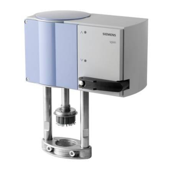
ACVATIX™
Electromotive actuators for
combi valves
For combi valves VPF43.. and VPF53..
∂
SQV91.. Operating voltage
Positioning signal
∂
Position feedback and selection of flow characteristic
∂
Manual adjuster, position and status indication (LED)
∂
Selectable positioning times 40-240 seconds
∂
Fail-safe function (combi valve open/closed)
∂
Selection of acting direction
∂
Optional functional extension: Auxiliary switch, potentiometer, and
AC 230 V module
∂
Direct mounting on combi valves
∂
UL approved
Electromotive actuators to operate Siemens combi valves for type series VPF43..
and VPF53.. with 20/40/43 mm stroke, as control valves for ventilation, air
conditioning, district heating and refrigeration plants.
AC/DC 24 V,
3-position, DC 0-10 V, DC 4-20 mA
Building Technologies
4
833
SQV..P..
Advertisement

Related Manuals for Siemens ACVATIX SQV91P30


Summarization of Contents
ACVATIX
TM Electromotive actuators for combi valves
Use and Application
Electromotive actuators for Siemens combi valves VPF43.. and VPF53.., used in ventilation and HVAC applications.
Product Variants and Configuration
Type Summary
Overview of actuator types, stock numbers, stroke, force, voltage, signal, and timing specifications.
Electrical Accessories
Details on auxiliary switch pairs, potentiometers, and AC 230V modules.
Ordering Information
Guidance on ordering actuators and accessories, including example configurations.
Equipment Combination
Details on compatible combi valves (VPF43.., VPF53..) and their flow rates.
Technology and Mechanical Design
Actuator Overview and Components
Description of actuator components, including manual adjuster, stem coupling, and status LEDs.
Operating Modes and Fail-Safe
Explanation of auto mode, manual mode, and actuator behavior during power loss.
Initialization and Control Signals
Details on automatic calibration, 3-position control signals, and acting direction.
Actuator Operation and Signals
Acting Direction Control
How to reverse the actuator's acting direction by exchanging connections or changing signals.
Positioning Signals Yu and Yi
Explanation of continuous positioning signals DC 0-10 V (Yu) and DC 4-20 mA (Yi).
Advanced Functions and Diagnostics
Position Feedback U
Description of position feedback signal U and its relation to actuator stroke.
Fail-Safe Function
Details on actuator behavior during power loss, including stem movement and locking time.
Recalibration Procedure
Manual procedure for triggering actuator recalibration using the manual adjuster.
Blockade Detection
How the actuator detects and reacts to blockages, and recovery of normal function.
Status Indication and End Position Response
Response at End Positions
Actuator behavior and LED indication when reaching end positions Ho and H100.
LED Status Indication
Interpretation of LED flashes and steady lights for initialization, mode, and errors.
Frost Protection Thermostat
Note on operating actuators with frost protection thermostats or temperature detectors.
DIL Switch Configuration
Positioning Times Configuration
Setting actuator positioning times (40-240 seconds) based on speed using DIL switches.
Flow Characteristics Configuration
Selecting linear or logarithmic flow characteristics via DIL switches for specific signals.
Accessories and Installation
Accessory Details
Detailed specifications for auxiliary switches, potentiometers, and AC 230V modules.
Engineering Notes
Important notes regarding electrical connections, safety regulations, and parallel operation.
Mounting Instructions
Guidelines for mounting actuators and accessories, referencing specific instruction manuals.
Operation and Maintenance
Mounting Positions
Diagrams showing acceptable mounting orientations for the actuator.
Commissioning and Maintenance
Steps for initial setup, functional checks, and regular maintenance.
Repair and Disposal
Information on spare parts availability, repair policy, and electronic waste disposal.
Technical Data
Power Supply Specifications
Details on operating voltage, frequency, and power consumption.
Function and Signal Data
Information on positioning times, force, stroke, and signal inputs.
Environmental and Compatibility Data
Climatic conditions, norms, directives, and environmental compatibility.
Dimensions and Connection Diagrams
Actuator Dimensions
Overall physical dimensions of the actuator and mounting clearances.
Connection Diagrams
Wiring examples for AC/DC 24 V and AC 230 V systems with various signal types.
Connection Terminals
Terminal Assignments DC 0-10V/4-20mA
Detailed description of terminal functions for DC signals and 3-position control.
Terminal Assignments AC 230V
Detailed description of terminal functions for AC 230V module with DC and 3-position signals.
Dimensions and Revision Numbers
Mounting Distance Specifications
Minimum mounting distances required for installation, operation, and maintenance.
Revision History
List of revision numbers and their corresponding versions for the actuator types.
Need help?
Do you have a question about the ACVATIX SQV91P30 and is the answer not in the manual?
Questions and answers