Advertisement
Quick Links
s
Use
CE1N4833en
2017-11-15
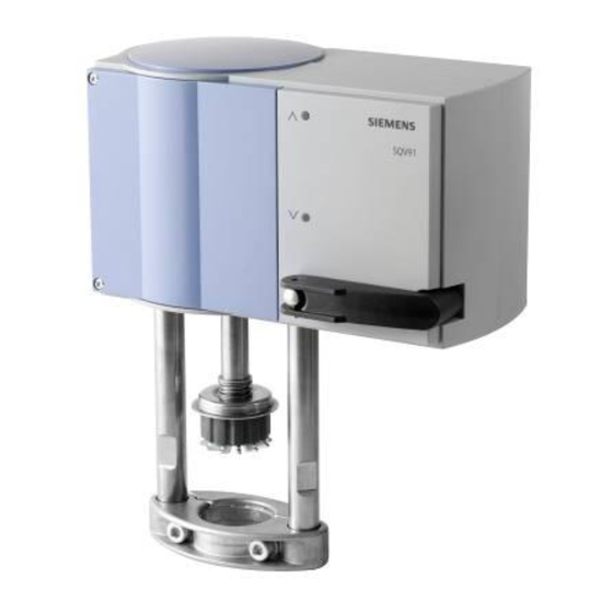
ACVATIX™
Electromotive actuators for
combi valves
For combi valves VPF43.. and VPF53..
∂
SQV91.. Operating voltage
Positioning signal
∂
Position feedback and selection of flow characteristic
∂
Manual adjuster, position and status indication (LED)
∂
Selectable positioning times 40-240 seconds
∂
Fail-safe function (combi valve open/closed)
∂
Selection of acting direction
∂
Optional functional extension: Auxiliary switch, potentiometer, and
AC 230 V module
∂
Direct mounting on combi valves
∂
UL approved
Electromotive actuators to operate Siemens combi valves for type series VPF43..
and VPF53.. with 20/40/43 mm stroke, as control valves for ventilation, air
conditioning, district heating and refrigeration plants.
AC/DC 24 V,
3-position, DC 0-10 V, DC 4-20 mA
Building Technologies
4
833
SQV..P..
Advertisement

Related Manuals for Siemens ACVATIX SQV91P40


Summarization of Contents
Electromotive actuators for combi valves
Use
Details the application of actuators for Siemens combi valves in HVAC systems.
Type summary
Electrical accessories
Lists available electrical accessories for the actuators.
Spare parts, rev. number
States that no spare parts are available and refers to revision numbers.
Ordering
Provides an example of how to order the actuator and accessories.
Delivery
Notes that actuators, valves, and accessories are packed individually.
Equipment combination
Details compatibility between actuators and specific Siemens combi valves.
Technology/Mechanical design
Auto mode
Describes the automatic operation where the manual adjuster is disengaged.
Manual mode
Explains manual operation using the adjuster, with motor switched off.
Initialization, automatic coupling, calibration
Details the automatic calibration process upon initial power supply.
3-position control signal
Explains how to control the actuator using 2-wire or 3-wire signals.
Changeover of acting direction
Explains how to reverse the stroke direction by swapping connections.
Positioning signals Yu and Yi
Details the use of continuous positioning signals DC 0-10V and DC 4-20mA.
Position feedback U
Describes the position feedback signal proportional to actuator stroke.
Fail-safe function
Explains actuator behavior during power loss and spring return.
Recalibration
Details the procedure for manually triggering recalibration.
Blockade detection
Explains how the actuator detects and reacts to blockages.
Response at the end positions
Describes actuator behavior and LED indications at end positions.
Status and acting direction indication (LED)
Details the meaning of LED indications for status and operation.
Configuration Settings
DIL switch Positioning times
Explains how to set positioning times using the DIL switch.
DIL switch Flow characteristics
Details setting flow characteristics (linear/logarithmic) via DIL switch.
Accessories and Installation
Accessories
Lists and describes available accessories like switch pairs and modules.
Engineering
Provides notes on electrical connections, safety, and controller compatibility.
Mounting
Refers to mounting instructions for actuators and accessories.
Mounting positions
Illustrates permissible mounting orientations for the actuator.
Commissioning
Outlines checks for wiring, functional testing, and settings during commissioning.
Maintenance
Provides recommendations for regular checks and servicing procedures.
Repair
States that spare parts are unavailable and actuators must be replaced.
Disposal
Provides guidelines for electronic device disposal according to EU directives.
Warranty
States warranty conditions related to connected Siemens valves.
Note
Warns about using third-party valves and Siemens' responsibility.
Technical data
Power supply
Details operating voltage, frequency, and power consumption.
Function data
Lists positioning times, force, and medium temperature limits.
Signal inputs
Specifies available signal inputs (voltage, current) and their parameters.
Fail-safe function
Describes actuator behavior and spring return times on power loss.
Position feedback
Details the position feedback signal and load impedance.
Connecting cable
Specifies wire cross-sections, cable entry types and sizes.
Degree of protection
States the housing protection rating (IP) and insulation class.
Environmental conditions
Lists climatic conditions for operation, transport, and storage.
Norms and directives
Lists relevant norms, directives, and conformity standards.
Environmental compatibility
References product environmental declarations and RoHS compliance.
Dimensions and Connections
Dimensions
Provides overall dimensions and mounting distance information.
Accessories
Details specifications for accessories like potentiometers and modules.
Connection diagrams
Illustrates wiring diagrams for AC/DC 24 V and AC 230 V connections.
Connection terminals
Lists and explains the function of each connection terminal for various signals.
Physical and Revision Data
Dimensions
Shows detailed physical dimensions of the actuator.
Revision numbers
Lists revision numbers for different actuator types (SQV91P30, SQV91P40).
Need help?
Do you have a question about the ACVATIX SQV91P40 and is the answer not in the manual?
Questions and answers