Table of Contents
Troubleshooting

Related Manuals for Fronius MagicWave 3000 Comfort


Summary of Contents for Fronius MagicWave 3000 Comfort
- Page 1 / Perfect Charging / Perfect Welding / Solar Energy Operating Instructions TransTig 2200 / 2500 / 3000 / 4000 Spare parts list Comfort TIG Power source MagicWave 2200 / 2500 / 3000 / 4000 Comfort 42,0426,0063,EN 017-28062016...
- Page 3 Thank you for the trust you have placed in our company and congratulations on buying this high-quality Fronius product. These instructions will help you familiarise yourself with the product. Reading the instructions carefully will enable you to learn about the many different features it has to offer.
-
Page 5: Table Of Contents
Contents Safety rules ..............................Explanation of safety symbols ......................General ..............................Proper use ............................Environmental conditions........................Obligations of the operator........................Obligations of personnel ........................Mains connection ..........................Protecting yourself and others ......................Noise emission values .......................... Danger from toxic gases and vapours ....................Danger from flying sparks ........................ - Page 6 Automated TIG welding ........................MMA welding ............................Before installation and commissioning....................... Safety..............................Utilisation for intended purpose ......................Setup regulations ..........................Mains connection ..........................Start-up ..............................Safety..............................Remarks on the cooling unit ......................... General ..............................Connecting the gas cylinder........................Establishing a ground (earth) connection to the workpiece ..............Connecting the welding torch........................
- Page 7 Saving settings as a job ..........................General ..............................Preparation ............................Saving settings as a job ........................Finish saving job ........................... Setup settings The Setup menu ............................General ..............................Overview ............................... TIG setup ..............................Opening the TIG setup.......................... Changing welding parameters ......................Exiting TIG setup ..........................
- Page 8 Exiting AC setup ........................... 137 Welding parameters in AC setup ......................138 Job ................................139 General ..............................139 Opening the Job set-up menu....................... 139 Save / retrieve............................139 Overview ............................... 139 Optimising a job ............................140 Optimising a job ............................ 140 Renaming a job.............................
- Page 9 Circuit diagrams: MagicWave 2500 Comfort ..................... 206 Circuit diagrams: MagicWave 3000 Comfort ..................... 207 Circuit diagrams: MagicWave 4000 Comfort ..................... 208 Circuit diagrams: TransTig 2200 Comfort ....................210 Circuit diagrams: TransTig 2500 Comfort ....................211 Circuit diagrams: TransTig 3000 Comfort ....................212...
-
Page 11: Safety Rules
Safety rules Explanation of DANGER! Indicates immediate and real danger. If it is not avoided, death or se- safety symbols rious injury will result. WARNING! Indicates a potentially dangerous situation. Death or serious injury may result if appropriate precautions are not taken. CAUTION! Indicates a situation where damage or injury could occur. -
Page 12: Proper Use
Proper use The device is to be used exclusively for its intended purpose. The device is intended solely for the welding processes specified on the rating plate. Any use above and beyond this purpose is deemed improper. The manufac- turer shall not be held liable for any damage arising from such usage. Proper use includes: carefully reading and following all the instructions given in the operating instructions... -
Page 13: Obligations Of Personnel
Obligations of Before using the device, all persons instructed to do so undertake: personnel to observe the basic instructions regarding safety at work and accident prevention to read these operating instructions, especially the "Safety rules" section and sign to confirm that they have understood them and will follow them. Before leaving the workplace, ensure that people or property cannot come to any harm in your absence. -
Page 14: Noise Emission Values
Protective clothing refers to a variety of different items. Operators should: protect eyes and face from UV rays, heat and sparks using a protective visor and regulation filter. wear regulation protective goggles with side protection behind the protec- tive visor. wear stout footwear that provides insulation even in wet conditions. -
Page 15: Danger From Flying Sparks
The relevant material safety data sheets and manufacturer's specifications for the listed components should therefore be studied carefully. Flammable vapours (e.g. solvent fumes) should be kept away from the arc's radiation area. Danger from fly- Flying sparks may cause fires or explosions. ing sparks Never weld close to flammable materials. -
Page 16: Meandering Welding Currents
If the device is operated on a mains supply without a ground conductor and using a socket without a ground conductor contact, this will be deemed gross negligence. The manufacturer shall not be held liable for any damage arising from such usage. If necessary, provide an adequate earth connection for the workpiece. -
Page 17: Emc Measures
EMC measures In certain cases, even though a device complies with the standard limit values for emissions, it may affect the application area for which it was designed (e.g. when there is sensitive equipment at the same location, or if the site where the device is installed is close to either radio or television receivers). - Page 18 During operation Ensure that all covers are closed and all side panels are fitted properly. Keep all covers and side panels closed. The welding wire emerging from the welding torch poses a high risk of injury (piercing of the hand, injuries to the face and eyes, etc.). Therefore always keep the welding torch away from the body (devices with wire-feed unit) and wear suitable protective goggles.
-
Page 19: Factors Affecting Welding Results
Factors affecting The following requirements with regard to shielding gas quality must be met if welding results the welding system is to operate in a correct and safe manner: Size of solid matter particles < 40 μm Pressure dew point < -20 °C Max. -
Page 20: Safety Measures In Normal Operation
Before transporting the device, allow coolant to drain completely and detach the following components: Wire-feed unit Wirespool Shielding gas cylinder After transporting the device, the device must be visually inspected for dam- age before commissioning. Any damage must be repaired by trained service technicians before commissioning the device. -
Page 21: Commissioning, Maintenance And Repair
Commissioning, It is impossible to guarantee that bought-in parts are designed and manufac- maintenance and tured to meet the demands made of them, or that they satisfy safety require- repair ments. Use only original spare and wearing parts (also applies to standard parts). Do not carry out any modifications, alterations, etc. -
Page 22: Safety Symbols
(e.g. relevant product standards from the EN 60 974 series). Fronius International GmbH declares that the device complies with directive 2014/53/EU. The full text of the EU Declaration of Conformity is available from the following website: http://www.fronius.com Devices with the CSA test mark satisfy the requirements of the relevant stand- ards in Canada and the USA. -
Page 23: General Information
General information... -
Page 25: General
General Device concept The MagicWave (MW) 2200 / 2500 / 3000 / 4000 Comfort and Trans-Tig (TT) 2200 / 2500 / 3000 / 4000 Comfort TIG power sources are completely digitised, micropro- cessor-controlled inverter power sources. The modular design and potential for sys- tem add-ons ensure a high degree of flexi- bility. -
Page 26: System Components
System components General The TransTig and MagicWave power sources can be used with a wide variety of system add-ons and options. Overview (10) (11) System add-ons and options Item Description TIG robot welding torch Cold wire feeders with wire drive Power sources Cooling units Trolley with gas cylinder holder... -
Page 27: Control Elements And Connections
Control elements and connections... -
Page 29: Description Of The Control Panels
Description of the control panels General NOTE! Due to software updates, you may find that your device has certain func- tions that are not described in these operating instructions or vice versa. Individ- ual illustrations may also differ slightly from the actual controls on your device, but these controls function in exactly the same way. - Page 30 No. Function Process button for selecting the welding process depending on the mode that has been chosen 2-step mode/4-step mode: automatic cap-shaping; only available in conjunction with TIG AC welding TIG AC welding process TIG DC- welding process Manual metal arc welding mode: MMA AC welding process MMA DC- welding process MMA DC+ welding process...
-
Page 31: Transtig Comfort Control Panel
TransTig Comfort control panel (14) (13) (12) (11) (10) No. Function Pulse indicator lights up when the F-P set-up parameter has been set to a pulse frequency Spot welding indicator lights up when the SPt set-up parameter has been set to a spot welding time Cold wire-feed unit indicator lights up when a cold wire-feed unit is connected Display... - Page 32 No. Function (13) Left arrow key for navigating in the menu (14) HF (high frequency) ignition indicator lights up when the HF ignition welding parameter has been set to an interval for the high frequency pulses...
-
Page 33: Connections, Switches And Mechanical Components
Connections, switches and mechanical components MagicWave 2200 Comfort MagicWave 2200 Comfort - front MagicWave 2200 Comfort - rear No. Function Welding torch connection for connecting: the TIG welding torch the electrode cable for manual metal arc welding LocalNet connection standardised connection socket for system add-ons (e.g. remote control, JobMas- ter TIG welding torch, etc.) Handle Torch control connection... -
Page 34: Magicwave2500 / 3000 Comfort
MagicWave 2500 / 3000 Com- fort MagicWave 2500 / 3000 Comfort - front MagicWave 2500 / 3000 Comfort - rear No. Function Grounding (earthing) cable connection for connecting the grounding (earthing) cable LocalNet connection standardised connection socket for system add-ons (e.g. remote control, JobMas- ter TIG welding torch, etc.) Handle Torch control connection... -
Page 35: Magicwave4000 Comfort
MagicWave 4000 Comfort MagicWave 4000 MagicWave 4000 Comfort - front MagicWave 4000 Comfort - rear No. Function Mains switch for switching the power source on and off Welding torch connection for connecting the TIG welding torch Electrode holder connection for connecting the electrode cable for manual metal arc welding Torch control connection for connecting the control plug of a conventional welding torch input for the collision protection signal when a robot interface or field bus cou-... -
Page 36: Transtig2200 Comfort
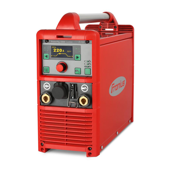
TransTig 2200 Comfort TransTig 2200 Comfort - front TransTig 2200 Comfort - rear No. Function (+) current socket with bayonet latch for connecting the grounding (earthing) cable when TIG welding the electrode cable or grounding (earthing) cable during MMA welding (de-... -
Page 37: Transtig2500 / 3000 Comfort
TransTig 2500 / 3000 Com- fort TransTig 2500 / 3000 Comfort - front TransTig 2500 / 3000 Comfort - rear No. Function (+) current socket with bayonet latch for connecting the grounding (earthing) cable when TIG welding the electrode cable or grounding (earthing) cable during MMA welding (de- pending on electrode type) LocalNet connection standardised connection socket for system add-ons (e.g. -
Page 38: Transtig4000 Comfort
TransTig 4000 Comfort TransTig 4000 TransTig 4000 Comfort - front TransTig 4000 Comfort - rear No. Function (+) current socket with bayonet latch for connecting the grounding (earthing) cable when TIG welding the electrode cable or grounding (earthing) cable during MMA welding (de- pending on the type of electrode) LocalNet connection standardised connection socket for system add-ons (e.g. -
Page 39: Installation And Commissioning
Installation and commissioning... -
Page 41: Minimum Equipment Needed For Welding Task
Minimum equipment needed for welding task General Depending on which welding process you intend to use, a certain minimum equipment lev- el will be needed in order to work with the power source. The welding processes and the minimum equipment levels required for the welding task are then described. -
Page 42: Before Installation And Commissioning
Before installation and commissioning Safety WARNING! Incorrect operation or shoddy workmanship can cause serious injury or damage. All work described in this document must only be carried out by trained and qualified personnel. All functions described in this document must only be used by trained and qualified personnel. -
Page 43: Start-Up
Start-up Safety WARNING! An electric shock can be fatal. If the machine is plugged into the mains electricity supply during installation, there is a high risk of very serious in- jury and damage. Do not carry out any work on the device unless the mains switch is in the "O"... -
Page 44: Establishing A Ground (Earth) Connection To The Workpiece
Screw the pressure regulator onto the gas cylinder and tighten it When using a TIG welding torch with an integral gas connector: Use the gas hose to connect the pressure regulator to the shielding gas connection on the rear of the power source Tighten the union nut on the gas hose When using a TIG welding torch with no integral gas connector: Connect the TIG welding torch gas hose to the pressure regulator... -
Page 45: Welding
Welding... -
Page 47: Tig Modes
TIG modes Safety WARNING! Operating the equipment incorrectly can cause serious injury and damage. Do not use the functions described until you have thoroughly read and understood the following documents: these operating instructions all the operating instructions for the system components, especially the safe- ty rules See the "The Setup menu"... -
Page 48: 2-Step Mode
2-step mode Welding: Pull back and hold the torch trigger End of welding: Release the torch trigger NOTE! To work in 2-step mode after it has been selected, the SPt set-up param- eter must be set to "OFF" and the spot welding indicator on the control panel must not light up. -
Page 49: 4-Step Mode
4-step mode Welding start-up with starting current I : Pull back and hold the torch trigger Welding with main current I : Release the torch trigger Lowering to final current I : Pull back and hold the torch trigger End of welding: Release the torch trigger NOTE! For 4-step mode, the special 4-step- (SFS) set-up parameter must be set to "OFF". -
Page 50: Special 4-Step Mode: Variant 2
Special 4-step Variant 2 of the special 4-step mode is activated when the special 4-step SFS set-up pa- mode: rameter -is set to "2“. variant 2 Intermediate lowering takes place in variant 2 on the basis of the selected slope values - downslope t and upslope t down... -
Page 51: Special 4-Step Mode: Variant 4
Special 4-step Variant 4 of the special 4-step mode is activated when the SFS set-up parameter is set to mode: "4". variant 4 Welding start-up and welding: briefly pull back and release the torch trigger - the weld- ing current will rise at the specified upslope value from the starting current I until it reaches the main current value I Push forward and hold the torch trigger for intermediate lowering... -
Page 52: Cap Shaping And Cap Overloading
Cap shaping and cap overloading Cap shaping On MagicWave power sources, an auto- matic cap-shaping function is available for the TIG AC welding process: When the TIG AC welding process is selected, activate automatic cap- shaping The ideal cap for the specified diame- ter of the tungsten electrode is formed during welding start-up. -
Page 53: Tig Welding
TIG welding Safety WARNING! Operating the equipment incorrectly can cause serious injury and damage. Do not use the functions described until you have thoroughly read and understood the following documents: these operating instructions all the operating instructions for the system components, especially the safe- ty rules WARNING! An electric shock can be fatal. - Page 54 Upslope, 2-step mode Upslope, 4-step mode Unit Setting range 0,0 - 9,9 Factory setting IMPORTANT! The upslope is saved separately for 2-step and 4-step modes. Main current, 2-step mode Main current, 4-step mode Unit Setting range MW 2500 Comfort 3 - 250 TT 2500 Comfort 3 - 250 MW 3000 Comfort 3 - 300 TT 3000 Comfort 3 - 300...
- Page 55 Downslope, 2-step mode Downslope, 4-step mode Unit Setting range 0,0 - 9,9 Factory setting IMPORTANT! The downslope is saved separately for 2-step and 4-step modes. Final current, 2-step mode Final current, 4-step mode Unit % (of main current) Setting range 0 - 100 Factory setting only with MagicWave for the TIG AC welding process...
-
Page 56: Preparation
Make sure that the tungsten electrode does not touch any persons or electrically conductive or earthed parts (e.g. housing, etc.). Move the mains switch to the I position The starting sequence with the Fronius logo, current firmware version and Fronius in- ternet address is displayed for approx. 1 second:... -
Page 57: Tig Welding
TIG welding Press the Mode button to select the required TIG mode: 2-step mode 4-step mode The image for the TIG welding parameter is shown on the display: TIG welding parameters for 2-step mode (main current TIG welding parameters for 4-step mode (main current welding parameter selected) welding parameter selected) Only with MagicWave: Press the Mode button to select the required TIG mode:... - Page 58 For long hosepacks and if condensation forms when the device is left unused in a cold environment: purge protective gas shield and set the GPU set-up parameter to a time value Start welding (ignite the arc)
-
Page 59: Igniting The Arc
Igniting the arc General To ensure the best ignition sequence in the TIG AC welding process, the MagicWave pow- er sources take account of: the diameter of the tungsten electrode the current temperature of the tungsten electrode with reference to the preceding welding and weld-off times To ensure the ideal ignition sequence in TIG DC welding, MagicWave power sources are equipped with RPI (Reverse Polarity Ignition). -
Page 60: Touchdown Ignition
Increase the tilt angle of the torch and actuate the torch trigger according to the mode you have selected The arc ignites without the electrode touching down on the workpiece. Tilt the torch back into the normal posi- tion Carry out welding Touchdown igni- If the HFt setup parameter is set to OFF, HF ignition is deactivated. -
Page 61: End Of Welding
Actuate the torch trigger Shielding gas flows. Gradually tilt the welding torch up until the tungsten electrode touches the workpiece Raise the welding torch and move it into its normal position The arc ignites. Carry out welding End of welding Depending on the set mode, finish welding by releasing the torch trigger Wait for the set gas post-flow and hold welding torch in position over the end of the weld seam... -
Page 62: Special Functions And Options
Special functions and options Arc break watch- If the arc breaks and the current does not start to flow again within the time specified in the dog function set-up menu, the power source cuts out automatically. The service code "no | Arc" appears on the control panel. -
Page 63: Tig Pulsing
TIG pulsing The welding current set at the start of welding is not always ideal for the welding process as a whole: if the amperage is too low, the base material will not melt sufficiently, if overheating occurs, the liquid weld pool may drip. The TIG pulsing function (TIG welding with pulsing welding current) offers a remedy: a low ground current I-G rises steeply to the significantly higher pulse current I1 and, de- pending on the set dcY (duty cycle) time, drops back to the ground current I-G. -
Page 64: Tacking Function
Tacking function The tacking function is available for the TIG DC welding process. When a time period is specified for the tAC (tacking) set-up parameter, the tacking function is assigned to 2-step mode and 4-step mode. The operating sequence of the modes re- mains unchanged. -
Page 65: Tig Cold-Wire Welding
TIG cold-wire TIG cold-wire welding is only possible in conjunction with a cold wire- feed unit. welding Mode of operation of TIG cold-wire welding at a set pulse frequency when DC welding is selected: Current waveshape Wire feed speed curve 1/F-P down Legend:... -
Page 66: Mma Welding
MMA welding Safety WARNING! Operating the equipment incorrectly can cause serious injury and damage. Do not use the functions described until you have thoroughly read and understood the following documents: these operating instructions all the operating instructions for the system components, especially the safe- ty rules WARNING! An electric shock can be fatal. - Page 67 Main current: starting current < main current ("SoftStart") Main current: starting current = main current Main current: starting current > main current ("HotStart") Unit Setting range MW 2500 Comfort 3 - 250 TT 2500 Comfort 3 - 250 MW 3000 Comfort 3 - 300 TT 3000 Comfort 3 - 300 Factory setting To obtain optimum welding results, it will sometimes be necessary to adjust the arc-force...
-
Page 68: Preparation
(e.g. the housing etc.). Move the mains switch to the I position The starting sequence with the Fronius logo, current firmware version and Fronius in- ternet address is displayed for approx. 1 second:... -
Page 69: Manual Metal Arc Welding
(e.g. the housing etc.). Move the mains switch to the I position The starting sequence with the Fronius logo, current firmware version and Froni- us internet address is displayed for approx. 1 second: Use the right arrow key to select the relevant welding parameters... -
Page 70: Hotstart Function
If necessary, additional welding parameters can be set in the set-up menu: Press the menu key The relevant menu is displayed: Use the adjusting dial to select the desired set-up menu Open the selected set-up menu by pressing the adjusting dial Use the adjusting dial to select the welding parameter To change the welding parameter press the adjusting dial Change the welding parameter value using the adjusting dial... -
Page 71: Softstart Function
SoftStart function The SoftStart function is intended for basic electrodes. Ignition takes place at a low welding current. Once the arc is stable, the welding current continues to rise until it reaches the welding current command value. Benefits: I (A) Improved ignition properties for elec- trodes that ignite at low welding cur- rents... -
Page 72: Welding Job
Welding job Safety WARNING! Operating the equipment incorrectly can cause serious injury and damage. Do not use the functions described until you have thoroughly read and understood the following documents: these operating instructions all the operating instructions for the system components, especially the safe- ty rules WARNING! An electric shock can be fatal. - Page 73 Upslope, 2-step mode Upslope, 4-step mode Unit Setting range 0,0 - 9,9 Factory setting IMPORTANT! The upslope is saved separately for 2-step and 4-step modes. Main current, 2-step mode Main current, 4-step mode Unit Setting range MW 2500 Comfort 3 - 250 TT 2500 Comfort 3 - 250 MW 3000 Comfort 3 - 300 TT 3000 Comfort 3 - 300...
- Page 74 Downslope, 2-step mode Downslope, 4-step mode Unit Setting range 0,0 - 9,9 Factory setting IMPORTANT! The downslope is saved separately for 2-step and 4-step modes. Final current, 2-step mode Final current, 4-step mode Unit % (of main current) Setting range 0 - 100 Factory setting only with MagicWave for the TIG AC welding process...
-
Page 75: Welding Parameters For Rod Electrodes
If cold wire-feed unit option is available Unit m/min Setting range OFF / 0.1 - max. OFF / 3.9 - max. Factory setting Unit Setting range OFF - max. OFF - max. Factory setting Welding parame- ters for rod elec- trodes Starting current: starting current <... - Page 76 Main current: starting current < main current ("SoftStart") Main current: starting current = main current Main current: starting current > main current ("HotStart") Unit Setting range MW 2500 Comfort 3 - 250 TT 2500 Comfort 3 - 250 MW 3000 Comfort 3 - 300 TT 3000 Comfort 3 - 300 Factory setting To obtain optimum welding results, it will sometimes be necessary to adjust the arc-force...
-
Page 77: Preparation
Make sure that the tungsten electrode does not touch any persons or electrically conductive or earthed parts (e.g. housing, etc.). Move the mains switch to the I position The starting sequence with the Fronius logo, current firmware version and Fronius in- ternet address is displayed for approx. 1 second:... -
Page 78: Welding Job
Welding job Press Menu key The relevant main menu appears, e.g.: Use the adjusting dial to select "job" (turn the adjusting dial) Press the adjusting dial The menu items for the job will now appear: Use the adjusting dial to select 'Retrieve' (turn the adjusting dial) - Page 79 Press the adjusting dial The display now shows the last job that was selected: A free memory location is indicated as follows: Use the adjusting dial to select the desired job (turn the adjusting dial) To change welding parameters according to the job correction stored in the job: Use left and right arrow keys to select welding parameters Press the adjusting dial...
-
Page 80: Finishing The Welding Job
Press the adjusting dial The adjusted value of the selected welding parameter is applied Start welding Finishing the Finish welding welding job Press Menu key The main menu for the welding job appears: Use the adjusting dial to select "job" (turn the adjusting dial) Press the adjusting dial The menu items for an active job will now appear: Use the adjusting dial to select "Finish"... - Page 81 Press the adjusting dial The welding parameters are shown for the most recently selected method, e.g.: Starting current 2-step mode...
-
Page 82: Saving Settings As A Job
Saving settings as a job General In the individual welding processes, settings and welding parameters can be stored in 100 jobs (job numbers 0 to 99). Preparation Select the mode to be saved using the Mode button: TIG 2-step mode TIG 4-step mode Manual metal arc welding mode The relevant image for the welding parameters is displayed, e.g.:... -
Page 83: Saving Settings As A Job
Change the welding parameter value using the adjusting dial Press the adjusting dial Press Menu key The latest menu appears, e.g.: Saving settings NOTE! When settings are saved as a job, all the settings are stored in the welding as a job parameters as well as in the relevant set-up menus in a job. - Page 84 Turn the adjusting dial to select the job number under which the settings are to be stored Press the adjusting dial If there is memory available, then the settings will be stored under the selected job number. If all the memory is occupied, then a warning prompt will appear. Free memory: The second "Save job"...
- Page 85 In order to delete letters / numbers, turn the adjusting dial and select 'Del': Press the adjusting dial to delete the last character: Press the button on the right (OK) in order to accept the name The settings will be stored and the third 'Save job' screen will appear: Press the button on the right (OK) The job numbers overview appears:...
- Page 86 Allocated memory: A warning prompt will appear: Press the button on the left or right: Left button (No): Do not overwrite job, return to job numbers overview Right button (Yes): Store settings under the chosen job number: The "Name job" screen appears: If necessary, delete the existing job name: Turn the adjusting dial and select 'Del' Press the adjusting dial to delete the last character:...
-
Page 87: Finish Saving Job
Then press the adjusting dial in order to enter these letters / numbers: Press the button on the right (OK) in order to accept the name The settings will be stored and the "Job saved" screen will appear: Press the button on the right (OK) The job numbers overview appears: Finish saving job Press Menu key... - Page 88 Press the adjusting dial The menu items for the job will now appear: Press Menu key Select the arrow symbol by turning the adjusting dial Press the adjusting dial The current set-up menu is displayed: Press Menu key Select the arrow symbol by turning the adjusting dial The current welding parameters are displayed e.g.: TIG welding parameters for 2-step mode (main current welding parameter selected)
-
Page 89: Setup Settings
Setup settings... -
Page 91: The Setup Menu
The Setup menu General The set-up menu provides easy access to the knowledge base in the power source and to additional functions. The set-up menu can be used to make simple adjustments of the welding parameters to suit the various job settings. The set-up menu contains all the set-up parameters that have an immediate effect on the welding process. -
Page 92: Tig Setup
TIG setup Opening the TIG Press the Mode button to select 2-step mode or 4-step mode setup The image for the TIG welding parameter is shown on the display: TIG welding parameters for 2-step mode TIG welding parameters for 4-step mode Press Menu key The main menu appears: Use the adjusting dial to select "TIG setup"... -
Page 93: Changing Welding Parameters
Changing weld- Select the desired welding parameter by turning the adjusting dial: ing parameters To set the welding parameter, press the adjusting dial The value of the selected welding parameter can now be changed: Change the welding parameter value by turning the adjusting dial: To apply the welding parameter value press the adjusting dial... -
Page 94: Exiting Tig Setup
Exiting TIG setup Press Menu key Select the arrow symbol by turning the adjusting dial Press the adjusting dial The main menu appears: Press Menu key Select the arrow symbol by turning the adjusting dial Press the adjusting dial The image for the TIG welding parameter is shown: TIG welding parameters for 2-step mode TIG welding parameters for 4-step mode... -
Page 95: Welding Parameters In The Tig Setup
Welding parame- "Minimum" and "maximum" are used for setting ranges that differ according to power ters in the TIG set- source, wire-feed unit, welding program, etc. Spot welding time Unit Setting range OFF / 0.05 - 25.0 Factory setting If a value has been set for the spot welding time, "2-step mode" will work in the same way as spot welding mode. - Page 96 Duty Cycle The ratio of pulse duration to base current duration when a pulse frequency has been set Unit Setting range 10 - 90 Factory setting Ground current Unit % (of main current I Setting range 0 - 100 Factory setting Starting current time Unit Setting range...
-
Page 97: Tig Setup 2Nd
TIG setup 2nd Opening the TIG Opening the TIG setup setup 2nd Select the 'TIG setup 2nd' parameter Press the adjusting dial The TIG setup 2nd parameters are shown: The power source is now in TIG setup 2nd Changing weld- Select the desired welding parameter by turning the adjusting dial: ing parameters To set the welding parameter, press the adjusting dial... -
Page 98: Exiting Tig Setup 2Nd
Change the welding parameter value by turning the adjusting dial: To apply the welding parameter value press the adjusting dial Exiting TIG setup Press Menu key Select the arrow symbol by turning the adjusting dial Press the adjusting dial The TIG setup parameters are shown:... - Page 99 Press Menu key Select the arrow symbol by turning the adjusting dial Press the adjusting dial The main menu appears: Press Menu key Select the arrow symbol by turning the adjusting dial Press the adjusting dial The image for the TIG welding parameter is shown: TIG welding parameters for 2-step mode TIG welding parameters for 4-step mode...
-
Page 100: Welding Parameters In The Tig Setup 2Nd
Welding parame- "Minimum" and "maximum" are used for setting ranges that differ according to power ters in the TIG set- source, wire-feed unit, welding program, etc. up 2nd Special 4-step Special 4-step mode Unit Setting range OFF / 1 - 3 Factory setting Variant 1 Variant 2... - Page 101 The special HF ignition indicator remains lit as long as a value has been specified for the HF ignition parameter. If the “HF ignition” set-up parameter is set to “OFF”, no high frequency ignition takes place at the start of welding. In this case, welding starts with touchdown ignition. rPI ignition Reversed polarity ignition Unit...
- Page 102 Ext. Parameter External parameter a user-defined welding parameter for the JobMaster TIG welding torch or robot interface (both optional). A freely selectable welding parameter is available both on the JobMaster TIG welding torch and for the robot interface. If “Ext. parameter” has been selected, you can use the adjusting dial to choose between the following possibilities for this freely definable weld- ing parameter: No freely defined welding parameter has...
-
Page 103: Ac Setup
AC setup General This setup is only available with MagicWave power sources. Open the AC set- Press the Mode button to select 2-step mode or 4-step mode The image for the TIG welding parameter is shown on the display: TIG welding parameters for 2-step mode TIG welding parameters for 4-step mode Press Menu key The main menu appears:... -
Page 104: Changing Welding Parameters
Press the adjusting dial The AC setup parameters are shown: The power source is now in AC setup. Changing weld- Select the desired welding parameter by turning the adjusting dial: ing parameters To set the welding parameter, press the adjusting dial The value of the selected welding parameter can now be changed: Change the welding parameter value by turning the adjusting dial: To apply the welding parameter value press the adjusting dial... -
Page 105: Exiting Ac Setup
Exiting AC setup Press Menu key Select the arrow symbol by turning the adjusting dial Press the adjusting dial The main menu appears: Press Menu key Select the arrow symbol by turning the adjusting dial Press the adjusting dial The image for the TIG welding parameter is shown: TIG welding parameters for 2-step mode TIG welding parameters for 4-step mode... -
Page 106: Welding Parameters In Ac Setup
Welding parame- "Minimum" and "maximum" are used for setting ranges that differ according to power ters in AC setup source, wire-feed unit, welding program, etc. AC frequency Unit Setting range Syn / 40 - 250 Factory setting for mains synchronisation of two power sources for simultaneous AC welding. -
Page 107: Ac Setup 2Nd
AC setup 2nd General This setup is only available with MagicWave power sources. Opening the AC Open the AC setup setup 2nd Select the 'AC setup 2nd' parameter Press the adjusting dial The AC setup 2nd parameters are shown: The power source is now in AC setup 2nd. Changing weld- Select the desired welding parameter by turning the adjusting dial: ing parameters... -
Page 108: Exiting Ac Setup 2Nd
Change the welding parameter value by turning the adjusting dial: To apply the welding parameter value press the adjusting dial Exiting AC setup Press Menu key Select the arrow symbol by turning the adjusting dial Press the adjusting dial The AC setup parameters are shown:... - Page 109 Press Menu key Select the arrow symbol by turning the adjusting dial Press the adjusting dial The main menu appears: Press Menu key Select the arrow symbol by turning the adjusting dial Press the adjusting dial The image for the TIG welding parameter is shown: TIG welding parameters for 2-step mode TIG welding parameters for 4-step mode...
-
Page 110: Welding Parameters In Ac Setup 2Nd
Welding parame- "Minimum" and "maximum" are used for setting ranges that differ according to power ters in AC setup source, wire-feed unit, welding program, etc. Pos half-wave positive half-wave Unit Setting range Tri / Sin / Rec / Off Factory setting Triangular waveform Sine ... -
Page 111: Gas Setup
Gas setup General The gas setup offers easy access to the protective gas shield settings. Opening the gas Press the Mode button to select 2-step mode or 4-step mode setup The image for the TIG welding parameter is shown on the display: TIG welding parameters for 2-step mode TIG welding parameters for 4-step mode Press Menu key... -
Page 112: Changing Welding Parameters
Press the adjusting dial The gas setup parameters are shown: The power source is now in gas setup. Changing weld- Select the desired welding parameter by turning the adjusting dial: ing parameters To set the welding parameter, press the adjusting dial The value of the selected welding parameter can now be changed: Change the welding parameter value by turning the adjusting dial: To apply the welding parameter value press the adjusting dial... -
Page 113: Exiting Gas Setup
Exiting gas setup Press Menu key Select the arrow symbol by turning the adjusting dial Press the adjusting dial The main menu appears: Press Menu key Select the arrow symbol by turning the adjusting dial Press the adjusting dial The image for the TIG welding parameter is shown: TIG welding parameters for 2-step mode TIG welding parameters for 4-step mode... -
Page 114: Gas Setup Parameters
Gas setup param- "Minimum" and "maximum" are used for setting ranges that differ according to power eters source, wire-feed unit, welding program, etc. Pre-flow Gas pre-flow time Unit Setting range 0,0 - 9,9 Factory setting Post-flow lmin Post-flow at I Gas post-flow time at minimum welding current (minimum gas post-flow time) Unit Setting range... - Page 115 Legend: (1)..Gas post-flow time at any given mo- ment (2)..Welding current at any given mo- ment G-H..Post-flow lmax G-L ..Post-flow lmin Gas post-flow time as a function of the welding current Gas qtity Command value for protective gas shield flow (only with the "digital gas control" option) Unit l/min Setting range...
-
Page 116: Cold Wire Setup
Cold wire setup General The cold wire setup is only available if a cold wire feeder is connected to the power source. Opening the AC Press the Mode button to select 2-step mode or 4-step mode setup The image for the TIG welding parameter is shown on the display: TIG welding parameters for 2-step mode TIG welding parameters for 4-step mode Press Menu key... -
Page 117: Changing Welding Parameters
Press the adjusting dial The cold wire setup welding parameters are shown: The power source is now in the cold wire setup. Changing weld- Select the desired welding parameter by turning the adjusting dial: ing parameters To set the welding parameter, press the adjusting dial The value of the selected welding parameter can now be changed: Change the welding parameter value by turning the adjusting dial: To apply the welding parameter value press the adjusting dial... -
Page 118: Exiting The Cold Wire Setup
Exiting the cold Press Menu key wire setup Select the arrow symbol by turning the adjusting dial Press the adjusting dial The main menu appears: Press Menu key Select the arrow symbol by turning the adjusting dial Press the adjusting dial The image for the TIG welding parameter is shown: TIG welding parameters for 2-step mode TIG welding parameters for 4-step mode... -
Page 119: Welding Parameters In The Cold Wire Setup
Welding parame- "Minimum" and "maximum" are used for setting ranges that differ according to power ters in the cold source, cold wire-feed unit, welding program, etc. wire setup Wirefeed spd2 Wire feed speed 2 Unit % (of the wire feed speed) Setting range 0 - 100 Factory setting... -
Page 120: Calibrating Push-Pull Unit
Calibrating push-pull unit General The push-pull unit must be calibrated before it is started up for the first time and whenever the wire feed software is updated. If the push-pull unit is not calibrated, standard welding parameters will be used - which may lead to an unsatisfactory welding result. Calibrating the For an overview of the service codes used during calibration of the push-pull unit, please push-pull unit... - Page 121 Press the right button The third push-pull calibration screen is shown: Follow the instructions shown CAUTION! Risk of injury from rotating cogs and drive parts. Keep hands away from rotating cogs and the wire drive. Press the right button The fourth push-pull calibration screen is shown: Follow the instructions shown CAUTION! Risk of injury from welding wire emerging at speed and from rotating cogs and drive parts.
-
Page 122: General
30 m/min or 1181 ipm Fronius VR 1530 KD Fronius Robacta KD Drive 10 m/min or 394 ipm Fronius Robacta Plasma KD Drive Fronius Robacta Laser KD Drive Fronius Robacta KD Drive 22 m/min or 866 ipm Fronius Robacta Plasma KD Drive... - Page 123 St1 | E 2, St1 - E5 Cause: At maximum wire feed speed, the wire-feed motor does not deliver any actual rotational speed value. Remedy: Repeat the push-pull calibration. If the error message re-appears: Contact After-Sales Service. Cause: At minimum wire feed speed, the motor of the push-pull unit does not deliver any actual rotational speed value.
- Page 124 Cause: At minimum wire feed speed, the motor current of the wire-feed unit motor is outside the permitted range. Possible reasons are dis- engaged wire-feed unit motors or wire feed problems. Remedy: Engage the drive units of both wirefeeder motors, arrange the hosepack in as straight a line as possible;...
- Page 125 Cause: At maximum wire feed speed, the motor current of the wire-feed unit motor is outside the permitted range. Possible reasons are dis- engaged wire-feed unit motors or wire feed problems. Remedy: Engage the drive units of both wire-feed unit motors, arrange the hosepack in as straight a line as possible;...
-
Page 126: Rod Elec. Setup (Rod Electrode Setup)
Rod elec. setup (rod electrode setup) Open the rod Press the Mode button to select the MMA welding mode electrode setup The image for the rod electrode welding parameter is shown on the display, e.g.: Press Menu key The main menu appears: Use the adjusting dial to select "Rod elec. -
Page 127: Changing Welding Parameters
Changing weld- Select the desired welding parameter by turning the adjusting dial: ing parameters To set the welding parameter, press the adjusting dial The value of the selected welding parameter can now be changed: Change the welding parameter value by turning the adjusting dial: To apply the welding parameter value press the adjusting dial... -
Page 128: Exiting Rod Electrode-Setup
Exiting rod elec- Press Menu key trode-setup Select the arrow symbol by turning the adjusting dial Press the adjusting dial The main menu appears: Press Menu key Select the arrow symbol by turning the adjusting dial Press the adjusting dial The image for the rod electrode welding parameter is shown:... -
Page 129: Rod Electrode Setup Parameters
Rod electrode "Minimum" and "maximum" are used for setting ranges that differ according to power setup parame- source, wire-feed unit, welding program, etc. ters: HotStart time Unit Setting range 0 - 2,0 Factory setting To obtain optimum welding results, it will sometimes be necessary to adjust the hotstart function. -
Page 130: Rod Elec. Setup 2Nd (Rod Electrode Setup 2Nd)
Rod elec. setup 2nd (rod electrode setup 2nd) Opening the rod Open the rod electrode setup electrode setup Select the 'rod electrode setup 2nd' parameter Press the adjusting dial The parameters for rod electrode setup 2nd are shown: The power source is now in rod electrode setup 2nd Changing weld- Select the desired welding parameter by turning the adjusting dial: ing parameters... -
Page 131: Exiting Rod Electrode Setup 2Nd
Change the welding parameter value by turning the adjusting dial: To apply the welding parameter value press the adjusting dial Exiting rod elec- Press Menu key trode setup 2nd Select the arrow symbol by turning the adjusting dial Press the adjusting dial The rod electrode setup parameters are shown:... - Page 132 Press Menu key Select the arrow symbol by turning the adjusting dial Press the adjusting dial The main menu appears: Press Menu key Select the arrow symbol by turning the adjusting dial Press the adjusting dial The image for the TIG welding parameter is shown:...
-
Page 133: Rod Electrode Setup 2Nd Parameters
Rod electrode "Minimum" and "maximum" are used for setting ranges that differ according to power setup 2nd param- source, wire-feed unit, welding program, etc. eters Anti-stick Unit Setting range ON / OFF Factory setting As the arc becomes shorter, the welding voltage may drop so far that the rod electrode will tend to stick. - Page 134 NOTE! When setting a flat characteristic (5), set the arc-force dynamic to a higher value. "P" parameter (constant welding power) If the “P” parameter is set, the welding power is kept constant, irrespective of the weld- ing voltage and welding current. This results in a hyperbolic characteristic (6). The “P”...
- Page 135 Break-voltage Welding voltage limitation Unit Setting range OFF or 5 - 90 V Factory setting The arc length depends on the welding voltage. To end the welding process, it is usually necessary to significantly lift the rod electrode away from the workpiece. With the “Uco” parameter, the welding voltage can be limited to a value that makes it possible to end the welding operation simply by slightly lifting the rod electrode.
-
Page 136: Ac Setup (For Rod Electrodes)
AC setup (for rod electrodes) General This setup is only available with MagicWave power sources. Opening the AC Press the Mode button to select the MMA welding mode setup The image for the rod electrode welding parameter is shown on the display, e.g.: Press Menu key The main menu appears:... -
Page 137: Changing Welding Parameters
Changing weld- Select the desired welding parameter by turning the adjusting dial: ing parameters To set the welding parameter, press the adjusting dial The value of the selected welding parameter can now be changed: Change the welding parameter value by turning the adjusting dial: To apply the welding parameter value press the adjusting dial Exiting AC setup Press Menu key... -
Page 138: Welding Parameters In Ac Setup
Press the adjusting dial The main menu appears: Press Menu key Select the arrow symbol by turning the adjusting dial Press the adjusting dial The image for the rod electrode welding parameter is shown: Welding parame- "Minimum" and "maximum" are used for setting ranges that differ according to power ters in AC setup source, wire-feed unit, welding program, etc. -
Page 139: Job
General The following actions can be performed in the Job set-up menu: Save: Save settings as a job Retrieve: Retrieve jobs for the welding job Retrieve: Adjust and modify stored jobs Delete: Delete stored jobs Opening the Job Press Menu key set-up menu The main menu appears, e.g.: Use the adjusting dial to select "job"... -
Page 140: Optimising A Job
Optimising a job Optimising a job Use the adjusting dial to select '"optimise" (turn the adjusting dial) Press the adjusting dial The first "Optimise job" screen or the last job to be selected or saved ap- pears: Example job Press the adjusting dial to select the job The job to be optimised can now be selected:... - Page 141 Use the adjusting dial to select the number of the job to be optimised (turn the adjusting dial) Press the adjusting dial The welding parameters for the job to be optimised appear: Turn the adjusting dial to select the welding parameters to be modified, e.g.: Press the adjusting dial The value of the selected welding parameter can now be changed:...
-
Page 142: Renaming A Job
Change the welding parameter value by turning the adjusting dial: To apply the welding parameter value press the adjusting dial Renaming a job In the "Optimise job" menu item, turn the adjusting dial to select "Job name" Press the adjusting dial The "Name job"... - Page 143 If you press the adjusting dial the last character will be deleted: Turn the adjusting dial to select the desired letters / numbers: Then press the adjusting dial in order to enter these letters / numbers: Press the button on the right (OK) in order to accept the name The new job name is applied and the "Optimise job"...
-
Page 144: Finish Optimising Job
Finish optimising Press Menu key Select the arrow symbol by turning the adjusting dial Press the adjusting dial The menu items for the job appear: Press Menu key Select the arrow symbol by turning the adjusting dial Press the adjusting dial The current set-up menu is displayed:... -
Page 145: Adjustable Tig Parameters
Press Menu key Select the arrow symbol by turning the adjusting dial Press the adjusting dial The current welding parameters will appear, e.g.: TIG welding parameters for 2-step mode (main current welding parameter selected) Adjustable TIG Electrode diam. parameters Electrode diameter Unit Setting range Off / 0.1 - 4.8... - Page 146 Final current Unit % (of main current) Setting range 0 - 100 Jobslope For changing to another job during welding. Jobslope is the time that it takes for the weld- ing current to adjust seamlessly from the present job to the next. Unit Setting range Off / 0.1 - 9.9...
- Page 147 Legend: (1)..Gas post-flow time at any given mo- ment (2)..Welding current at any given mo- ment G-H..Post-flow lmax G-L ..Post-flow lmin Gas post-flow time as a function of the welding current If Aut is selected, the gas post-flow time is calculated automatically. This takes the select- ed process (AC or DC welding) into account.
- Page 148 Polarity Unit Setting range AC (only MagicWave) / DC- / DC+ AC frequency only with MagicWave for the TIG AC welding process Unit Setting range Syn / 40 - 250 for mains synchronisation of two power sources for simultaneous AC welding. IMPORTANT!If using the "Syn"...
- Page 149 Final current time Unit Setting range OFF / 0.01 - 9.9 The final current time t-E specifies the duration of the final current phase I IMPORTANT!The final current time only applies in 2-step mode. In 4-step mode, the du- ration of the final current phase I is controlled with the torch trigger (see: "TIG operating modes").
-
Page 150: Adjustable Rod Electrode Parameters
End-delay Delay in the start of wirefeeding from end of the main current phase Unit Setting range OFF / 0.1 - 9.9 Wire wdraw Unit Setting range OFF / 1 - 50 OFF / 0.04 - 1.97 IMPORTANT!Wire withdrawal prevents the welding wire from burning at the end. Before the welding current is switched off, the wire is withdrawn to the set value. - Page 151 Starting curr time Unit Setting range OFF / 0.01 - 9.9 The starting current time t-S specifies the duration of the starting-current phase I Char For selecting characteristics Unit Setting range con or 0.1 - 20 or P Factory setting Load line for rod electrode Load line for rod electrode where arc length is in- con - 20 A / V...
- Page 152 Load line for rod electrode Load line for rod electrode where arc length is in- creased U (V) Load line for rod electrode where arc length is re- duced Characteristic where "CON" parameter is select- ed (constant welding current) Characteristic where "0.1 - 20" parameter is se- lected (drooping characteristic with adjustable slope) Characteristic where "P"...
- Page 153 AC frequency only with MagicWave for the TIG AC welding process Unit Setting range Syn / 40 - 250 For mains synchronisation of two power sources for simultane- ous AC welding. IMPORTANT! If using the "Syn" setting, remember to check the "Phase sync." parameter in AC setup 2nd.
-
Page 154: Deleting A Job
Deleting a job Deleting a job Use the adjusting dial to select "Delete" (turn the adjusting dial) Press the adjusting dial The first "Delete job" screen is displayed: Turn the adjusting dial to select the job for deletion: Press the right button The second "Delete job"... - Page 155 The third "Delete job" screen is displayed: Press the right button The menu items for the job appear: Press Menu key Select the arrow symbol by turning the adjusting dial Press the adjusting dial The current set-up menu is displayed:...
- Page 156 Press Menu key Select the arrow symbol by turning the adjusting dial Press the adjusting dial The current welding parameters are displayed e.g.: TIG welding parameters for 2-step mode (main current welding parameter selected)
-
Page 157: Basic Setting
Basic setting General The basic settings can be called up in the menu when TIG 2-step mode, TIG 4-step mode or manual metal arc welding mode is selected. Opening the ba- Press Menu key sic settings The main menu appears: TIG main menu Rod electrode main menu Use the adjusting dial to select "Basic setting"... -
Page 158: Changing Welding Parameters
Changing weld- Select the desired welding parameter by turning the adjusting dial: ing parameters To set the welding parameter, press the adjusting dial The value of the selected welding parameter can now be changed: Change the welding parameter value by turning the adjusting dial: To apply the welding parameter value press the adjusting dial... -
Page 159: Exiting Basic Settings
Exiting basic set- Press Menu key tings Select the arrow symbol by turning the adjusting dial Press the adjusting dial The relevant main menu appears: TIG main menu Rod electrode main menu Press Menu key Select the arrow symbol by turning the adjusting dial... -
Page 160: Basic Setting Parameters
Press the adjusting dial The image for the currently selected mode is shown, e.g.: TIG welding parameters for 2-step mode Basic setting pa- "Minimum" and "maximum" are used for setting ranges that differ according to power rameters source, cold wire-feed unit, welding program, etc. Language Unit Setting range... -
Page 161: Info
Info General The info screen can be called up in the menu when TIG 2-step mode, TIG 4-step mode or rod electrode welding mode is selected. Calling up the Press Menu key info screen The main menu appears: TIG main menu Rod electrode main menu Use the adjusting dial to select "Info"... -
Page 162: Exiting The Info Screen
Exiting the info Press Menu key screen Select the arrow symbol by turning the adjusting dial Press the adjusting dial The relevant main menu appears: TIG main menu Rod electrode main menu Press Menu key Select the arrow symbol by turning the adjusting dial... -
Page 163: Entries On The Info Screen
Press the adjusting dial The image for the currently selected mode is shown, e.g.: TIG welding parameters for 2-step mode Entries on the Firmware info screen Current display/control panel firmware UST Software Current software of the power source control board UST Arc burn time Arc time Actual total arc burn time since using for the first time... -
Page 164: Lock Keys
Lock keys General To prevent welding parameters or settings from being changed either intentionally or unin- tentionally, the 'Lock keys' function can be activated on the power source. Lock keys Press Menu key The main menu appears: TIG main menu Rod electrode main menu Use the adjusting dial to select "Lock keys"... -
Page 165: Unlock Keys Again
Unlock keys Press Menu key again The 'Lock/unlock keys' screen appears: Press the key on the right (OK) within 3 seconds The keys are unlocked and the image for the currently selected mode is shown, e.g.: TIG welding parameters for 2-step mode (main current welding parameter selected) -
Page 166: Factory - For Resetting The Welding Machine
Factory - for resetting the welding machine General The welding machine can be reset in the menu when TIG 2-step mode, TIG 4-step mode or rod electrode welding mode is selected. NOTE! When the welding machine is reset, all the personal settings in the set-up menu are lost. -
Page 167: L/R Alignment
L/R alignment L = Welding circuit inductivity, H (Microhenry) Abbreviations R = Welding circuit inductivity, mOhm (Milliohm) General informa- The way that the hosepack is arranged has a very significant effect on the weld properties. tion on welding Particularly with pulsed-arc welding and AC welding, a high welding circuit inductivity may circuit inductivity occur, depending on the length of the hosepack and on the way that it is arranged. -
Page 168: L/R Alignment
L/R alignment Calibration of welding circuit inductivity and resistance can be done both in TIG setup 2nd and rod electrode setup 2nd. NOTE! L/R alignment must be carried out separately for each welding process. Enter TIG setup 2nd or rod electrode setup 2nd Select 'L/R align.' by turning the adjustment dial: Press the adjusting dial The first L/R alignment screen is displayed:... - Page 169 Press the right button After R/L alignment, a confirmation and the current welding circuit resistance will be shown: Press the right button Depending on the mode selected, TIG setup 2nd or rod electrode setup 2nd is displayed:...
-
Page 171: Troubleshooting And Maintenance
Troubleshooting and maintenance... -
Page 173: Troubleshooting
Troubleshooting General The digital power sources are equipped with an intelligent safety system. This means that apart from the fuse for the coolant pump, it has been possible to dispense with fuses en- tirely. After a possible malfunction or error has been remedied, the power source can be put back into normal operation again without any fuses having to be replaced. - Page 174 E2 - E4 Cause: Overtemperature in the second- ary circuit of the power source Remedy: Allow power source to cool down E5 - E10 Cause: Overtemperature in the primary circuit of the power source Remedy: Allow power source to cool down Cause: Temperature sensor fault (short circuit or break)
- Page 175 Cause: Overtemperature in the control circuit Remedy: Allow power source to cool down If the power source is being used with a robot interface or a field bus Cause: Robot not ready Remedy: Initialise "Robot ready" signal, ini- tialise "Source error reset" signal (N.B.
- Page 176 Cause: Mains overvoltage: The mains voltage has exceeded the upper limit of the tolerance range (see section "Technical data") Remedy: Check the mains voltage Cause: The earth current watchdog has triggered the safety cut-out of the power source. Remedy: Switch off the power source, wait for 10 seconds and then switch it on again.
- Page 177 Cause: Overtemperature on TP 08 re- mote control Remedy: Allow TP 08 remote control to cool down Cause: Interface fault Remedy: Contact After-Sales Service Cause: Thermostat on cooling unit has tripped Remedy: Wait until the end of the cooling phase, i.e. until "Hot | H2O" is no longer displayed.
- Page 178 Cause: The upper voltage limit was ex- ceeded Remedy: Check welding parameters Cause: The voltage dropped below the lower limit Remedy: Check welding parameters Cause: The welding device configuration has been changed Remedy: Check LHSB link Cause: No connection to power source Remedy: Check connection to power source and its software...
-
Page 179: Service Codes Displayed In Conjunction With The Digital Gas Control Option
Service codes Cause: The gas watchdog option has de- displayed in con- tected that there is no gas pres- junction with the sure digital gas control Remedy: Check protective gas shield sup- option ply, connect new gas cylinders or gas cylinder valves/open gas pressure regulator Displayed Service The following abbreviations are used for the service codes shown in conjunction with cold... -
Page 180: Power Source - Troubleshooting
Power source - Power source does not function troubleshooting Mains switch is on, but indicators are not lit up Cause: There is a break in the mains lead; the mains plug is not plugged in Remedy: Check the mains lead, ensure that the mains plug is plugged in Cause: Mains socket or mains plug faulty Remedy:... - Page 181 No protective gas shield All other functions are OK Cause: Gas cylinder is empty Remedy: Change the gas cylinder Cause: Gas pressure regulator is faulty Remedy: Change the gas pressure regulator Cause: Gas hose is not fitted or is damaged Remedy: Fit or change the gas hose Cause:...
-
Page 182: Care, Maintenance And Disposal
Care, maintenance and disposal General Under normal operating conditions, the power source requires only a minimum of care and maintenance. However, it is vital to observe some important points to ensure it remains in a usable condition for many years. Safety WARNING! Work that is carried out incorrectly can cause serious injury or dam- age. -
Page 183: Disposal
Disposal Dispose of in accordance with the applicable national and local regulations. -
Page 185: Appendix
Appendix... -
Page 187: Technical Data
Technical data Special voltages NOTE! An inadequately dimensioned electrical installation can cause serious damage. The mains cable and its fuse must be dimensioned accordingly. The technical data shown on the rating plate applies. MagicWave MW 2200 Comfort 2200 Comfort Mains voltage 230 V Mains voltage tolerance -20 % / +15 %... -
Page 188: Magicwave2500 / 3000 Comfort
MagicWave MW 2500 Comfort MW 3000 Comfort 2500 / 3000 Com- Mains voltage 3 x 400 V 3 x 400 V fort Mains voltage tolerance ± 15 % ± 15 % Mains frequency 50/60 Hz 50/60 Hz Mains fuse protection (slow-blow) 16 A 16 A Mains connection... -
Page 189: Magicwave 2500 / 3000 Comfort Mv
MagicWave MW 2500 Comfort MW 3000 Comfort 2500 / 3000 Com- fort MV Mains voltage 3 x 200 - 240 V 3 x 200 - 240 V 3 x 400 - 460 V 3 x 400 - 460 V 1 x 200 - 240 V 1 x 200 - 240 V Mains voltage tolerance ±... -
Page 190: Magicwave 4000 Comfort, Magicwave 4000 Comfort Mv
MW 2500 Comfort MW 3000 Comfort Dimensions L x W x H (with handle) 560 / 250 / 435 mm 560 / 250 / 435 mm 22.0 / 9.8 / 17.1 in. 22.0 / 9.8 / 17.1 in. Weight 28,2 kg 30 kg 62.17 lb. -
Page 191: Transtig 2200 Comfort
TransTig TT 2200 Comfort 2200 Comfort Mains voltage 230 V Mains voltage tolerance -20 % / +15 % Mains frequency 50 / 60 Hz Mains fuse protection (slow-blow) 16 A Mains connection No restrictions Primary continuous power (100% d.c. 3,0 kVA Cos phi 0,99 Welding current range... -
Page 192: Transtig2500 / 3000 Comfort
TransTig TT 2500 Comfort TT 3000 Comfort 2500 / 3000 Com- Mains voltage 3 x 400 V 3 x 400 V fort Mains voltage tolerance ± 15 % ± 15 % Mains frequency 50/60 Hz 50/60 Hz Mains fuse protection (slow-blow) 16 A 16 A Mains connection... -
Page 193: Transtig 2500 / 3000 Comfort Mv
TransTig TT 2500 Comfort MV TT 3000 Comfort MV 2500 / 3000 Com- Mains voltage 3 x 200 - 240 V 3 x 200 - 240 V fort MV 3 x 400 - 460 V 3 x 400 - 460 V 1 x 200 - 240 V 1 x 200 - 240 V Mains voltage tolerance... -
Page 194: Transtig 4000 Comfort, Transtig 4000 Comfort Mv
TT 2500 Comfort MV TT 3000 Comfort MV Dimensions L x W x H (with handle) 560 / 250 / 435 mm 560 / 250 / 435 mm 22.0 / 9.8 / 17.1 in. 22.0 / 9.8 / 17.1 in. Weight 25,9 kg 25,9 kg... -
Page 195: Spare Parts And Circuit Diagrams
Spare parts and circuit diagrams... -
Page 196: Spare Parts List: Transtig / Magicwave 2200 Comfort
Spare parts list: TransTig / MagicWave 2200 Comfort... -
Page 198: Spare Parts List: Transtig / Magicwave 2500 / 3000
Spare parts list: TransTig / MagicWave 2500 / 3000... - Page 199 43,0004,3830 - 26pol. 4,070,963,Z - UST-PIPE 4,071,201,Z 4,071,068,Z 43,0001,3320 43,0006,0168 43,0006,0168 4,071,063,Z 33,0010,0366 4,071,064,Z - MV 33,0010,0367 4,071,065,Z - MW2500 4,071,066,Z - MW3000 4,071,071 - TT3000 42,0409,3196 - MW 42,0409,3195 - TT 43,0001,3318 - TT 2500/3000 43,0001,3319 - MW 2500/3000 4,070,812,Z - HFF22 33,0010,0377-TT2500 43,0001,3311 - MW...
-
Page 200: Spare Parts List: Transtig 4000
Spare parts list: TransTig 4000... -
Page 202: Spare Parts List: Magicwave 4000
Spare parts list: MagicWave 4000... -
Page 205: Circuit Diagrams: Magicwave 2200 Comfort
Circuit diagrams: MagicWave 2200 Comfort V. 12.06.2014... -
Page 206: Circuit Diagrams: Magicwave 2500 Comfort
Circuit diagrams: MagicWave 2500 Comfort... -
Page 207: Circuit Diagrams: Magicwave 3000 Comfort
Circuit diagrams: MagicWave 3000 Comfort... -
Page 208: Circuit Diagrams: Magicwave 4000 Comfort
Circuit diagrams: MagicWave 4000 Comfort V 17.12.2012... - Page 209 V 17.12.2012...
-
Page 210: Circuit Diagrams: Transtig 2200 Comfort
Circuit diagrams: TransTig 2200 Comfort V 14.12.2010... -
Page 211: Circuit Diagrams: Transtig 2500 Comfort
Circuit diagrams: TransTig 2500 Comfort... -
Page 212: Circuit Diagrams: Transtig 3000 Comfort
Circuit diagrams: TransTig 3000 Comfort... -
Page 213: Circuit Diagrams: Transtig 4000 Comfort
Circuit diagrams: TransTig 4000 Comfort V 17.12.2012... - Page 216 FRONIUS INTERNATIONAL GMBH Froniusplatz 1, A-4600 Wels, Austria Tel: +43 (0)7242 241-0, Fax: +43 (0)7242 241-3940 E-Mail: sales@fronius.com www.fronius.com www.fronius.com/addresses Under http://www.fronius.com/addresses you will find all addresses of our Sales & service partners and Locations...
Need help?
Do you have a question about the MagicWave 3000 Comfort and is the answer not in the manual?
Questions and answers