
Related Manuals for Fronius FPA 3020 Orbital


Summary of Contents for Fronius FPA 3020 Orbital
- Page 1 / Perfect Welding / Solar Energy / Perfect Charging Translated document: FPA 3020 Orbital Operating instructions, Spare parts list TIG power source 42,0426,0232,EN V11 - 07042020...
- Page 3 Read the manual carefully and you will soon be familiar with all the many great features of your new Fronius product. This really is the best way to get the most out of all the advantages that your machine has to offer.
-
Page 5: Table Of Contents
Contents Safety rules ..............................9 General remarks............................9 Utilisation for intended purpose only ......................9 Ambient conditions ........................... 10 Obligations of owner/operator ........................10 Obligations of personnel .......................... 10 Mains connection ............................. 10 Protection for yourself and other persons ....................11 Information on noise emission values ...................... - Page 6 Start-up Before commissioning ........................... 39 Utilisation in accordance with ........................39 „intended purpo- se“ ..........................39 Setup regulations ............................. 39 Mains connection ............................. 39 Generator- powered operati- on ....................... 39 Commissioning .............................. 40 Safety ............................... 40 Note regarding the cooling unit ........................ 40 Connecting gas cylinders for shielding gas and forming gas ..............
- Page 7 Wire inching.............................. 69 Date, time and calibrating the touchscreen ....................70 Parameter settings ............................71 Calling up the „Parameter settings“ menu ....................71 Waveform parameters for TIG manual torch .................... 71 Waveform parameters for orbital weld head .................... 72 Parameters for pulsing and welding speed ....................72 Parameters for pulsing and ........................
-
Page 9: Safety Rules
Safety rules General remarks This equipment has been made in accordance with the state of the art and all recognised safety rules. Nevertheless, incorrect operation or misuse may still lead to danger for the life and well-being of the operator or of third parties, the equipment and other tangible assets belonging to the owner/operator, efficient working with the equipment. -
Page 10: Ambient Conditions
Ambient Operation or storage of the power source outside the stipulated range is deemed to be conditions “not in accordance with the intended use”. The manufacturer shall not be liable for any damage resulting herefrom. Temperature range of ambient air: when operating: - 10 °C to + 40 °C (14 °F to 104 °F) when being transported or stored: - 25 °C to + 55 °C (-13 °F to 131 °F) Free of dust, acids, corrosive gases or substances etc. -
Page 11: Protection For Yourself And Other Persons
Protection for When welding, you are exposed to many different hazards such as: yourself and arc radiation which could damage your eyes and skin other persons harmful electromagnetic fields which may put the lives of cardiac pace- maker users at risk electrical hazards from mains and welding current increased exposure to noise noxious welding fumes and gases. -
Page 12: Hazards From Mains And Welding Current
Hazards from An electric shock is potentially life-threatening, and can be fatal. mains and Do not touch any live parts, either inside or outside the machine. welding current In TIG welding, the welding wire, the wire spool, the drive rollers and all metal parts having contact with the welding wire are also live. -
Page 13: Emc Measures
EMC measures In certain cases, even though a device complies with the standard limit values for emissions, it may affect the application area for which it was designed (e.g. when there is sensitive equipment at the same location, or if the site where the device is installed is close to either radio or television receivers). -
Page 14: Particular Danger Spots
Particular danger Keep your hands, hair, clothing and tools well away from all moving parts, e.g.: spots fans toothed wheels, rollers, shafts wire-spools and welding wires ► Do not put your fingers anywhere near the rotating toothed wheels of the wirefeed drive. -
Page 15: Danger From Shielding-Gas Cylinders
Danger from Shielding-gas cylinders contain pressurized gas and may explode if they are damaged. shielding-gas As shielding-gas cylinders are an integral part of the overall welding outfit, they also have cylinders to be treated with great care. Protect shielding-gas cylinders containing compressed gas from excessive heat, me- chanical impact, slag, naked flames, sparks and arcs. -
Page 16: Safety Precautions In Normal Operation
Safety precau- Only operate the machine if all of its protective features are fully functional. If tions in normal any of the protective features are not fully functional, this endangers: operation the life and well-being of the operator or other persons the equipment and other tangible assets belonging to the owner/operator efficient working with the equipment. -
Page 17: Safety Inspection
Safety inspection The owner/operator is obliged to have a safety inspection performed on the machine at least once every 12 months. The manufacturer also recommend the same (12-month) interval for regular calibration of power sources. A safety inspection, by a trained and certified electrician, is prescribed: after any alterations after any modifications or installations of additional components following repairs, care and maintenance... -
Page 19: General Information
General information... -
Page 21: General
General Principle The FPA 3020 is a completely digitised, microprocessor-controlled inverter power source for orbital welding. An active power source manager is coupled with a digital signal processor, and together they control and regulate the entire welding process. The actual data are measured continuously, and the device responds immediately to any changes. -
Page 22: Warning Notices Affixed To The Device
A number of safety symbols can be seen on the device’s rating plate. affixed to the The safety symbols must NOT be removed or painted over. device FPA 3020 Part No. 8,040,098 www.fronius.com XXXXXXXX Ser.No. IEC 60974-1/-10 Cl.A 5 A / 10.2 V - 200 A / 18.0 V X(40°C) 100%... -
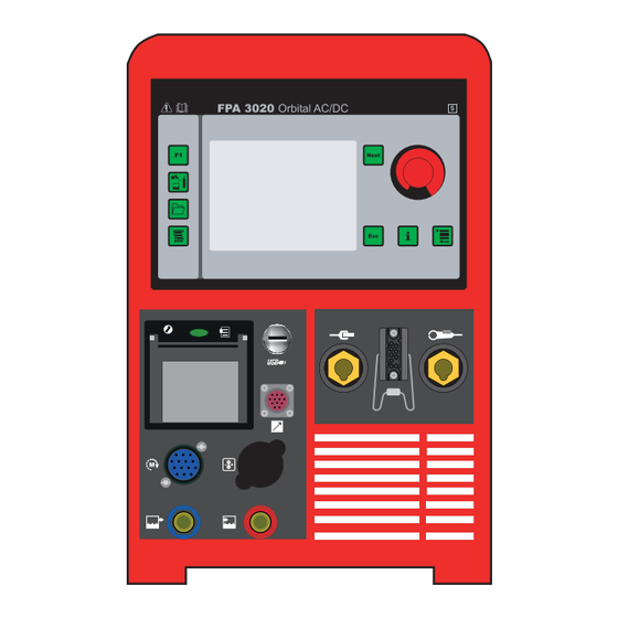
Page 23: Controls And Connections
Controls and connections Control panel WARNING! Operating the equipment incorrectly can cause serious injury and damage Do not use the functions described here until you have read and completely understood all of the following documents: These operating instructions all operating instructions for the system components, especially the “Safety rules”... - Page 24 Control panel Function (continued) „Next“ key for scrolling to the next menu window Touchscreen Displays various context-sensitive keypads F1 key freely programmable function key (in the „setup and system parameter“ menu) Shielding gas and cooling key Opens the „shielding gas and cooling“ menu Data exchange key Opens the data transfer menu Printer configuration key...
-
Page 25: Symbol Bar
Symbol bar WARNING! Operating the equipment incorrectly can cause serious injury and damage Do not use the functions described here until you have read and completely understood all of the following documents: These operating instructions all operating instructions for the system components, especially the “Safety rules”... - Page 26 Symbol bar Clockwise welding direction Anti-clockwise welding direction (continued) Welding off/no arc (black - test Welding on/with arc (blue) mode) Shielding gas valve not active Shielding gas valve active (blue) Forming gas valve not active Forming gas valve active (blue) Limit switch for closed orbital Limit switch for closed orbital welding gun not active...
-
Page 27: Connections, Switches And System Add-Ons
Connections, switches and system add-ons Safety WARNING! Operating the equipment incorrectly can cause serious injury and damage Do not use the functions described here until you have read and completely understood all of the following documents: These operating instructions all operating instructions for the system components, especially the “Safety rules”... - Page 28 Power source Function FPA 3020 Orbital welding gun control connection (continued) for data capture, control and motor supply of the orbital welding gun Water flow connection for the orbital welding gun or the TIG welding torch (10) Water return connection for the orbital welding gun or the TIG welding torch (11) Torch control connection for a standard TIG welding torch or orbital welding gun with additional controls...
-
Page 29: Remote Control Unit
(11) (12) Remote controller FPA 3020 Group selection key FRONIUS Press (+) or (-) to access the selection menu to select the _ _ _ _ _ _ _ _ _ _ _ _ _ _ _ _ program group... - Page 30 Remote control Program selection key FRONIUS unit (continued) Press (+) or (-) to select the _ _ _ _ _ _ _ _ _ _ _ _ _ _ _ _ desired welding program (a) from CrNi_21,0x1,5 the group previously selected (b) using key (3).
- Page 31 Remote control Arc on/off button unit If the LED in the key (8) lights up, the arc will come on for welding. The arc can (continued) also be switched off for setting up purposes. In addition, dialog window 1 in the “Troubleshooting”...
- Page 32 Remote control (12) Stop button unit Pressing key (12) stops welding immediately. (continued) IMPORTANT! Regardless of the settings in the “Parameter settings” menu, weld- ing stops with no downslope when key (12) is pressed. For all orbital welding guns: Pressing key (12) and the “left” key (13) at the same time sets the present position of the orbital welding gun to zero.
-
Page 33: Display Idle
Display idle Date and time 04.12.15 10:20:57 Name of the currently loaded welding CrNi_40.0x1.5 program Orbital welding gun type READY/NOT READY - power source FCH-6-76 ready to weld, or error needs to be READY Seg 1 rectified Seg 1 status indicator for current segment Wirespeed Pos - position of the orbital welding gun [°] / welding speed [cm/min]... -
Page 34: Display During Upslope
Display during Number appearing next to START, UPSLO upslope „START, UPSLO“ is the time elapsed since welding started Pos/D Seg 1 status indicator for current segment Speed cm/min Curr position of the orbital welding gun [°] Volt welding speed [cm/min] welding current [A] Volt welding voltage [V]... -
Page 35: Display After Welding Is Cancelled
Display after If welding was interrupted because of an alarm, or because Start/Stop, Stop or welding is Emergency stop was pressed, the following appears: cancelled Date and time 04.12.15 10:20:57 Orbital welding gun type Start —> CONTINUE FCH-6-76 press Start/ Stop (11) to start welding R+Stop —>... -
Page 37: Start-Up
Start-up... -
Page 39: Before Commissioning
Risk of fatal injury from dangerous electrical voltage. An electric shock can be fatal. Connection to the mains supply may only be done by Fronius technicians. The manufacturer assumes no responsibility for damage to persons or property caused by incorrect connection by the client. -
Page 40: Commissioning
Commissioning Safety DANGER! An electric shock can be fatal. If the device is plugged into the mains electricity supply during installation, there is a high risk of very serious injury and damage. Only carry out work on the device when the mains switch is in the „O“... -
Page 41: Establishing A Connection To The Workpiece
Connecting gas If using an orbital welding gun with an integral gas connector: cylinders for Using the gas hose, connect pressure regulator for shielding gas to the shielding shielding gas and gas input connection forming gas Tighten the union nut (continued) If available/required, connect pressure regulator for forming gas to the forming gas input connection using the gas hose. -
Page 42: Technical Data
Pollution degree according IEC 60664 EMC emission class Marks of conformity S, CE Dimensions L x W x H 650 x 290 x 480 mm 25.6 x 11.4 x 18.9 in Weight 38 kg 84 lb Coolant Original Fronius Sound power level (LWA) -
Page 43: Integral Cooling Unit
62.37 psi Pump type Centrifugal pump Coolant capacity 1,8 l Rating plate FPA 3020 Part No. 8,040,098 www.fronius.com XXXXXXXX Ser.No. IEC 60974-1/-10 Cl.A 5 A / 10.2 V - 200 A / 18.0 V X(40°C) 100% 44 V 200 A... -
Page 45: Operation
Operation... -
Page 47: Menus With Direct Selection
Menus with direct selection Principle You can call up individual menus directly using keys on the control panel. A detailed description of this menu is carried out on the following pages. Button F1 F1 calls up a user-defined function. The following functions are available:: Active alarm page Alarm history Move to starting position... -
Page 48: Data Transfer" Menu
„Shielding gas IMPORTANT! If the „OFF“ setting has been selected, the coolant pump will be in „AUTO“ and cooling“ mode after every power source restart provided that no gas-cooled welding torch is menu connected. (continued) To test the coolant pump 1. -
Page 49: Printer Configu- Ration" Menu
„Printer configu- Open the menu by pressing the „Printer configuration“ key ration“ menu Provide the following information: 1. Realvalue Printout“ for relevant process data Options include: ► No Print Out ► Printer Prints to paper using the integral printer ► USB Stick No printing occurs. - Page 50 „Printer configu- Example of „Realvalue Printout“ on paper: ration“ menu (continued) Example of „Realvalue Printout“ as a .txt file for USB stick:...
- Page 51 „Printer configu- Example of „Parameter Printout“ on paper: ration“ menu (continued)
- Page 52 „Printer configu- Example of „Parameter Printout“ as a .txt file for USB stick: ration“ menu (continued) Example of „Alarm Printout“ and „Start-Stop Printout“ on paper:...
- Page 53 „Printer configu- Example of „Alarm Printout“ and „Start-Stop Printout“ as .txt file for USB stick: ration“ menu (continued) If „Start-Stop Printout“ has been selected, the following is printed every hour:...
-
Page 54: Alarms And Device-Specific Data
Alarms and Open the menu by pressing the „i“ key device-specific data Version numbers of the main modules To display the present alarms, touch the „ALARMS“ button Current alarms These could be faults or application errors that have not yet been rectified. To display the saved alarms, touch the „HISTORY“... - Page 55 Alarms and In the first window, touch the „i“ key on the device-specific „HEAD.INFO“ button to call up the orbital data welding gun data. (continued) IMPORTANT! The fields contained in this window are not controls and are for display purposes only. Diameter min.
- Page 56 Alarms and WARNING! device-specific Operating the device incorrectly can cause serious injury and damage! data Do not use the functions described here until you have read and completely (continued) understood all of the following documents: these Operating Instructions all the operating instructions for the system components, especially the “Safety Rules”...
-
Page 57: Main Menu
Main menu Safety WARNING! Risk of injury and damage from electric shock! As soon as the mains switch is in the „I“ position, the tungsten electrode of the orbital welding gun is LIVE. Make sure that the tungsten electrode does not touch any persons or electrically conducting or earthed parts (e.g. -
Page 58: Selection Window
Selection window The selection window offers the following menus: Parameter settings Setup and system parameters Synergic (characteristic) Weld Orbital welding gun/manual welding torch IMPORTANT! If a TIG welding torch has been selected instead of the orbital welding gun, the following symbol appears (4) as follows: Entry shows the currently selected orbital welding gun or manual torch. -
Page 59: Orbital Welding Gun
Orbital welding gun Calling up the To select an orbital welding gun or welding torch, call up the orbital „orbital welding welding gun menu. gun“ menu Selecting the Select the desired type of orbital welding type of orbital gun: welding gun (a) Open orbital welding gun (b) Closed orbital welding gun (c) Manual welding torch... -
Page 60: Selecting The Type Of Manual Welding Torch
Selecting the For gas-cooled welding torches, call type of manual up the „GAS M. TORCH“ entry welding torch For water-cooled welding torches, select the „WATER M. TORCH“ entry IMPORTANT! For gas-cooled or water- cooled welding torches, Gas-cooled: standard setting for coolant pump is “OFF”. -
Page 61: Synergic
Synergic Calling up the Call up the „Synergic“ menu „Synergic“ menu Principle In synergic mode, it is sufficient merely to enter a few well-known settings for the arc process. Using this information, the power source calculates all other settings for an optimum welding result. -
Page 62: Parameter Tack.pr
Parameter Make the following settings in the „Tack TACK.PR Program“ window: „Tackpoints“ OFF - tacking deactivated 1 ..20 - number of tack points “Tack.Welding time” duration of welding current for a tack point [s] “Position 1st tack point” position of the first tack point [degrees] “Tack gas preflow“... -
Page 63: Setup And System Parameters
Setup and system parameters Calling up the Call up the „Setup and system para- meters“ menu „Setup and system parame- A detailed description of the menus is provided in the following ters“ menu sections. Principle The „Setup and system parameters“ menu allows users to adjust the power source and orbital welding gun specifically to their requirements. -
Page 64: Changing Password
User permissions If required, press the „RESET USER“ (4) button to reset the settings to their (continued) original status Use the „Op.-“ and „Op. +“ (5) buttons to call up the settings for others users Use the „BACK“ button to go back to the „Change Operator“ window In the „Change Operator“... -
Page 65: Logging On A Different User, And Changing The Password
Logging on a To call up a different pre-saved user different user, in order to log him on under his name, and changing the touch the „USER ++“ button. password If the password of the user that has just been logged on is to be changed: Touch button (1) Further details can be found in the section headed “Changing pass-... -
Page 66: Brightness And Contrast
Brightness and Using buttons (1) and (2), adjust contrast the brightness and contrast of the touchscreen Make the following settings in the input area (3): The numeric values to be entered correspond to the sequence of coloured boxes shown on the left. Example: „0“... -
Page 67: Welding Mode & Ac
Ignition “Ignition time out” parameters time until switch-off if no ignition occurs [s] To attempt ignition again, welding must (continued) be started again “Arc strike” time until switch-off after the arc has broken [s]. If the arc-break function is activated, clean the surface of the workpiece and start welding again “HF-pulse time”... -
Page 68: Value Adjustment
Stop button) at the start of a new weld.> Multilayer welds with different programs can be realized. Touch button “Fronius-Automation”(a) to bring up a keypad for entering text Use the „ROTATION“ button to call up the window for the rotation and welding... -
Page 69: Welding Direction And Wirefeeding
Welding direction Provide the following information: and wirefeeding Welding direction Clockwise Anti-clockwise IMPORTANT! Only closed welding guns with no wirefeeding support the anti- clockwise welding direction. Manual speed welding speed in manual mode [cm/min] Rapid motion speed high-speed welding [as % of the maximum welding speed of the orbital gun] Path adjustment path adjustment as a percentage. -
Page 70: Date, Time And Calibrating The Touchscreen
Date, time and In the „Set time“ window, you can provide calibrating the the following information: touchscreen Year Month Hour Minute Second Touch the “Set clock” button to apply the time set To calibrate the touchscreen Touch the „Calibration“ button Touch the crosshair Repeat this process until the “Set time”... -
Page 71: Parameter Settings
Parameter settings Calling up the Call up the „Parameter settings“ menu „Parameter settings“ menu Principle The parameter settings allow the user to enter or correct the most important parameters for the orbital welding process. Waveform para- Provide the following information: meters for TIG Step mode manual torch... -
Page 72: Waveform Parameters For Orbital Weld Head
Waveform Provide the following information: parameters for Welding path [degrees] orbital weld head Diameter External diameter of pipe join [mm] Offset for offsetting the start point of segment drawing in degrees [deg]. Offset has no influence on weld. IMPORTANT! Entering a figure higher than 360° will mean an overlap of the weld seam at the end of welding. I-S ... -
Page 73: Parameters For Pulsing And
Parameters for If required, adjust the segment path for each segment once more pulsing and The following parameters for the main current can be set individually for the welding speed segments: (continued) I-P ... Pulsing current [A] t-P ... Pulsing current time [ms] I-G ... -
Page 74: Parameters For Welding Energy
Parameters for RETURN TRAVEL start point ► NO (continued) ► WITH BACK TRAVEL After welding finishes, the orbital welding gun moves back to the start position ► ES-360 for closed welding guns with no external wirefeeding. After welding finishes, the orbital welding gun moves back to the limit switch. ► X-360 After welding finishes, the orbital welding gun takes the shortest path to the start and sets the angle for the travel path to zero ►... -
Page 75: Calling Up Parameters For Wirefeeding Or Ac Welding
Calling up para- IMPORTANT! If a TIG manual welding torch has been connected instead of the orbital meters for wire- welding gun, the corresponding windows differ slightly from the following illustrations. feeding or AC The parameters however are similar. welding Selecting the surface (a) calls up the settings for the main current again... -
Page 76: Parameters For Ac Welding
Parameters for Provide the following information: AC welding AC Frequency [Hz] SYNC for mains synchronisation of two power sources for simultaneous AC welding AC Balance -5: highest fusing power, lowest cleaning action +5: highest cleaning action, lowest fusing power Use the „POWER“ button to call up the settings for the main current again Use the „BACK“... - Page 77 Success After the „SELECT“ button has been programs touched, a screen opens for the group (continued) that contains the original welding program. Successor programs are selected here (c). The selected successor programs are listed under the original program (d). Use the << and >> buttons (e) to switch between programs.
-
Page 78: Orbital And Tig Welding
Orbital and TIG welding Safety DANGER! An electric shock can be fatal. If the device is plugged into the mains electricity supply during installation, there is a high risk of very serious injury and damage. Only carry out work on the device when the mains switch is in the „O“... -
Page 79: Welding Energy Status
Controlling and START monitoring the to start the welding process. welding process STOP (continued) to finish the welding, with down- slope IMPORTANT! If welding has to be stopped immediately, for safety reasons for example: Click the ABORT button. Welding stops immediately, with gas post-flow but no downslope IMPORTANT! If the „not ready“... -
Page 80: Welding Process Status
Welding process Status display of the following parameters: status ► PROCESS-ACTIVE-STATUS ► POWER SOURCE STATUS ► LIMIT SWITCH ACTIVE ► ALARM - STATUS FPA Correcting the This window appears when a change is made on the remote control. For every segment welding process (up to a maximum of 10) the latest change to the original value is shown. -
Page 81: Troubleshooting
Troubleshooting... -
Page 83: Troubleshooting
Troubleshooting General remarks In the event of faults, note that the function of the orbital system controller depends on many additional components (power source, orbital weld head, wire feed unit, ...) which are also potential sources of problems. All the service codes that are shown on the current source’s display device also appear on the orbital system controller’s touch- screen display. -
Page 84: Alarms And Error Messages
Retrieving alarm The following actions can be performed list from the tray screen: (continued) Open the active alarm page by touch- ing the „Alarmlist“ button IMPORTANT! For more detailed infor- mation on the alarms, please refer to the section headed “Alarms and error messages”. - Page 85 Alarms and error Group 002 messages (continued) Power source not ready LocalNet is sending data Limit exceeded LocalNet: Limit exceeded Torch collision LocalNet: Torch collision Gateway not ready LocalNet: Gateway not ready Wire sticking Wire stuck fast PS (service codes) For a detailed explanation of the service codes, please see the section headed “Service codes displayed”.
- Page 86 Alarms and error Group 004 (continued) messages (continued) IR: Emergency pressed The emergency stop button has activated a safety cut-out IR Stop key -> interrupt Welding was interrupted by the Stop button IR Alarm (see alarm page) Miscellaneous alarm IR Arc w/o main current signal Main current signal missing IR No arc signal Arc OK signal missing...
- Page 87 Alarms and error Group 006 messages (continued) Current Puls Limit Current Backg Limit Torch Voltage Limit Head speed Limit Wire speed Limit SA Limit high/low Alarm as per plain text display Applies to all alarms: Check how long and by how much the limit value has been exceeded.
-
Page 88: Error List Servo
Alarms and error To deactivate further error-related messages alarms: (continued) Touch the touchscreen. A symbol bar appears (a) Use the arrow keys (b) to select the alarm concerned Select the padlock symbol in the symbol bar (c) The alarm concerned is greyed out To reactivate the alarm, select it again using the arrow keys (b) touch the „padlock symbol“... -
Page 89: Alarms Information For Service Technicians
Alarms informat- To access the alarms for service technician, button press “i”. ion for service technicians In the first „i“ key window, touch the „SYSTEM“ button to call up more service-related information. Press the „INTERN“ button to call up the window shown below to display additional data... -
Page 90: Displayed Service Codes
Displayed service IMPORTANT! If an error message that is not described here appears on the displays, codes then the fault is one that can only be put right by a service engineer. Make a note of the error message shown in the display, and of the serial number and configuration of the po- wer source, and get in touch with our After-Sales Service, giving them a detailed descrip- tion of the error. -
Page 91: Displayed Service Codes Power Source
Displayed service no | Arc codes Power Cause: Arc-break source Remedy: Restart welding; clean workpiece surface. no | H2O Cause: Cooling unit flow watchdog has been triggered Remedy: Check the cooling unit; if necessary, top up the coolant or bleed the water flow as described in “Putting the cooling unit into service”... - Page 92 Displayed service No welding current codes Power Mains switch is ON and indicators are lit up source Cause: Incorrect earth connection (continued) Remedy: Check the earthing (grounding) connection and clamp for correct polarity Cause: Break in power cable in the orbital welding gun or welding torch. Remedy: Replace orbital welding gun or welding torch Nothing happens when welding starts...
- Page 93 Displayed service Orbital welding gun or torch gets very hot codes Power Cause: The design dimensions of the orbital welding gun or torch are not source sufficient for this task (continued) Remedy: Observe the duty cycle and loading limits Cause: Only on water-cooled machines: Water flow rate is insufficient Remedy: See “Water flow too low or non-existent”...
- Page 94 Displayed service Insufficient cooling codes Power Cause: Faulty ventilator source Remedy: Replace ventilator (continued) Cause: coolant pump defective. Remedy: Replace coolant pump Cause: Cooler contaminated Remedy: Blow out cooler with dry compressed air High operating noise level Cause: Coolant level too low Remedy: Top up with coolant Cause:...
-
Page 95: Maintenance And Disposal
Maintenance and disposal... -
Page 97: Care, Maintenance And Disposal
If no coolant is returning, check the cooling unit and bleed if necessary NOTE! If water-cooled torches are operated without coolant, this will normally result in a fault in the torch body or hosepack. Fronius shall not be liable for any damage resulting from such action. In addition, no warranty... -
Page 98: Symbols For Care And Maintenance Of The Cooling Unit
If the coolant level is below the „min“ mark, top up with coolant NOTE! Use only original Fronius coolant when filling cooling units. Other coolants are not recommended for electrical conductivity or compatibility re- asons. -
Page 99: Every 2 Months
Every 12 months After 12 months, drain the coolant and dispose of it properly IMPORTANT! Coolant must not be disposed of in the public sewage system. Use only original Fronius coolant (item no. 40,0009,0046) when refilling the cooling unit. -
Page 100: Disassembly And Disposal
Disassembly and disposal Disassembling Electrical equipment: the system DANGER! Risk of fatal injury from dangerous electrical voltage. The areas bearing this symbol contain parts that are under dangerous electrical voltages. Electrically-charged parts (capacitors) can remained charged for a considerable length of time after they are switched off. An electric shock can be fatal! Before opening the power source: Move the mains switch to the O position Switch off all supply leads and unplug them from the mains... -
Page 101: Spare Parts List
Spare parts list... - Page 103 FPA 3020 Orbital 8,040,098 see next page (15) (14) (13) (12) (11) (10) (16) (17) (18) (19) (20) (21) (22) (29) (23) (28) (24) (25) (27) (26) see next page FPA 3020 Orbital Spare parts list...
- Page 104 FPA 3020 Orbital 8,040,098 (48) (30) (42) (49) (43) (31) (41) (44) (50) (45) (46) (32) (51) (33) (52) (40) (47) (53) (34) (39) (35) (54) (38) (37) (36) (57) (55) (58) (56) (59) (61) (60) (64) (62) (65) (63)
- Page 105 FPA 3020 Orbital 8,040,098 Item Designation Type Item no. NT60 PC board 4,070,627 NTFK24 PC board 4,070,819 Power supply 230V - 24VDC/5,0A 38,0006,0141 PFC-Choke MW 2200 33,0010,0325 Fan 60x60x25 24V 43,0006,0168 Cooler 270X118X40 34,0450,0975 Fan 24V 17,5W 388m³/h 43,0006,0292 FMW22IS PC board...
- Page 106 FPA 3020 Orbital 8,040,098 Item Designation Type Item no. Quick connection AG R1/8´´ NW5 44,0001,1145 Nut KST red VST357/457 42,0405,0186 Quick connection AG R1/8´´ NW5 44,0001,1145 Nut KST blue VST357/457 42,0405,0187 Socket housing EB20 43,0003,0256 Dust cap 20 42,0407,0568 Thermal printer...
- Page 107 FPA 3020 Orbital 8,040,098 Item Designation Type Item no. Module X20DI6371 38,0009,0207 BM11 bus module X20BM11 38,0009,0138 Field terminal 12-polig 38,0009,0182 Module X20DC4395 38,0009,0134 BM11 bus module X20BM11 38,0009,0138 Field terminal 12-polig 38,0009,0182 Module X20CS1020 38,0009,0132 BM11 bus module X20BM11...
- Page 108 FPA 3020 Orbital Spare parts list...
- Page 109 FPA 3020 Orbital Spare parts list...
- Page 110 FPA 3020 Orbital Spare parts list...
- Page 111 FPA 3020 Orbital Spare parts list...
- Page 112 FPA 3020 Orbital Spare parts list...
-
Page 113: Eu-Declaration Of Conformity
EU-Declaration of conformity... - Page 115 FRONIUS INTERNATIONAL GMBH TechSupport Automation www.fronius.com www.fronius.com/addresses...
Need help?
Do you have a question about the FPA 3020 Orbital and is the answer not in the manual?
Questions and answers