Sign In
Upload
Download
Table of Contents
Contents
Add to my manuals
Delete from my manuals
Share
URL of this page:
HTML Link:
Bookmark this page
Add
Manual will be automatically added to "My Manuals"
Print this page
×
Bookmark added
×
Added to my manuals
Manuals
Brands
Canon Manuals
All in One Printer
Color iR C2550i
Service manual
Canon Color iR C2550i Service Manual
Hide thumbs
1
2
3
4
5
6
7
8
9
10
11
12
13
14
15
16
17
18
19
20
21
22
23
24
25
26
27
28
29
30
31
32
33
34
35
36
37
38
39
40
41
42
43
44
45
46
47
48
49
50
51
52
53
54
55
56
57
58
59
60
61
62
63
64
65
66
67
68
69
70
71
72
73
74
75
76
77
78
79
80
81
82
83
84
85
86
87
88
89
90
91
92
93
94
95
96
97
98
99
100
101
102
103
104
105
106
107
108
109
110
111
112
113
114
115
116
117
118
119
120
121
122
123
124
125
126
127
128
129
130
131
132
133
134
135
136
137
138
139
140
141
142
143
144
145
146
147
148
149
150
151
152
153
154
155
156
157
158
159
160
161
162
163
164
165
166
167
168
169
170
171
172
173
174
175
176
177
178
179
180
181
182
183
184
185
186
187
188
189
190
191
192
193
194
195
196
197
198
199
200
201
202
203
204
205
206
207
208
209
210
211
212
213
214
215
216
217
218
219
220
221
222
223
224
225
226
227
228
229
230
231
232
233
234
235
236
237
238
239
240
241
242
243
244
245
246
247
248
249
250
251
252
253
254
255
256
257
258
259
260
261
262
263
264
265
266
267
268
269
270
271
272
273
274
275
276
277
278
279
280
281
282
283
284
285
286
287
288
289
290
291
292
293
294
295
296
297
298
299
300
301
302
303
304
305
306
307
308
309
310
311
312
313
314
315
316
317
318
319
320
321
322
323
324
325
326
327
328
329
330
331
332
333
334
335
336
337
338
339
340
341
342
343
344
345
346
347
348
349
350
351
352
353
354
355
356
357
358
359
360
361
362
363
364
365
366
367
368
369
370
371
372
373
374
375
376
377
378
379
380
381
382
383
384
385
386
387
388
389
390
391
392
393
394
395
396
397
398
399
400
401
402
403
404
405
406
407
408
409
410
411
412
413
414
415
416
417
418
419
420
421
422
423
424
425
426
427
428
429
430
431
432
433
434
435
436
437
438
439
440
441
442
443
444
445
446
447
448
449
450
451
452
453
454
455
456
457
458
459
460
461
462
463
464
465
466
467
468
469
470
471
472
473
474
475
476
477
478
479
480
481
482
483
484
485
486
487
488
489
490
491
492
493
494
495
496
497
498
499
500
501
502
503
504
505
506
507
508
509
510
511
512
513
514
515
516
517
518
519
520
521
522
523
524
525
526
527
528
529
530
531
532
533
534
535
536
537
538
539
540
541
542
543
544
545
546
547
548
549
550
551
552
553
554
555
556
557
558
559
560
561
562
563
564
565
566
567
568
569
570
571
572
573
574
575
576
577
578
579
580
581
582
583
584
585
586
587
588
589
590
591
592
593
594
595
596
597
598
599
600
601
602
603
604
605
606
607
608
609
610
611
612
613
614
615
616
617
618
619
620
621
622
623
624
625
626
627
628
629
630
631
632
633
634
635
636
637
638
639
640
641
642
643
644
645
646
647
648
649
650
651
652
653
654
655
656
657
658
659
660
661
662
663
664
665
666
667
668
669
670
671
672
673
674
675
676
677
678
679
680
681
682
683
684
685
686
687
688
689
690
691
692
693
694
695
696
697
698
699
700
701
702
703
704
705
706
707
708
709
710
711
712
713
714
715
716
717
718
719
720
721
722
723
724
725
726
727
728
729
730
731
732
733
734
735
736
737
738
739
740
741
742
743
744
745
746
747
748
749
750
751
752
753
754
755
756
757
758
759
760
761
762
763
764
765
766
767
768
769
770
771
772
773
774
page
of
774
Go
/
774
Contents
Table of Contents
Troubleshooting
Bookmarks
Table of Contents
Table of Contents
Chapter 8 Pickup/Feeding System
Chapter 18 Upgrading
Chapter 1 Introduction
System Construction
System Configuration 1 (Delivery Accessories)
System Configuration Overview (Delivery Accessories)
System Configuration 2 (Delivery Accessories)
System Configuration 3 (Delivery Accessories)
System Configuration (Delivery Accessories)
System Configuration (Pickup/Original Processing Accessories)
Cassette Heater System Configuration 1
System Configuration (Printing/Transmission Accessories) (USA)
System Configuration (Printing/Transmission Accessories)
Functions of Printing/Transmission Accessories
Functions of Printing/Transmission Accessories (USA)
Other Options
Product Specifications
External View
Names of Parts
Cross Section
Points to Note about Turning off the Main Power Switch
Turning on the Power Switch
Using the Machine
Common Settings
User Mode Items
Common Settings
Adjustment/Cleaning
Timer Settings
Report Settings
System Settings
System Settings
Communications Settings
Copy Settings
Address Book Settings
Mail Box Settings
Cleaning
User Maintenance
Inspection
CDRH Act
Handling of Laser System
Laser Safety
Safety
Notes When Handling a Lithium Battery
Safety of Toner
Notes before It Works Serving
Product Specifications
Type and Function
Others
Function List
Others
Print Speed (Image)
Type of Paper
Type of Paper
Chapter 2 Installation
Making Pre-Checks
Selecting the Site of Installation
Check to Make before Installation
Combination Table of Accessory Installation
Checking the Contents
Unpacking and Installation
Installation of the Drum Unit
Installation of the Scanner
Unpacking
Installation of the Toner Retainer
Attaching Other Parts
Connection of the Cable
Points to Note When Turning off the Main Power
Automatic Gradation Correction
Fixing the Machine in Place
Setting up the Cassette
Adjusting the Image Position
Checking the Connection to the Network
Making Checks Using a Remote Host Address
Using PING
Troubleshooting the Network
Making a Check Using a Local Host Address
Making Checks Using a Loopback Address
Checking the Images/Operations
Checking the Images
Relocating the Machine
Installing the Copy Tray
Checking the Components
Installation Procedure
Turning off the Machine
Installing the Card Reader
Installation Procedure in the Imageware Accounting Manager (Hereinafter Referred to Iwam Environment
Installing the Original Tray
Installing the Key Switch Unit
Checking after Installation
Turning off the Host Machine
Installing the Voice Operation Kit
Turning off the Host Machine
Installing the Wireless Network Interface Adapter
Turning off the Host Machine
Affixing the Label
Cleaning the Copyboard Glass
Affixing Labels
Turning off the Host Machine
Construction/Basic Sequence
Construction
Functional Construction
Chapter 3 Basic Operation
Connections Among Major Pcbs
Basic Sequence
Basic Sequence of Operations at Power-On
Basic Sequence of Operations for a Print Job (Full Color)
Basic Sequence of Operations for a Print Job (Mono Color)
Table of Contents
Construction
Construction and Functions
Construction of the Electrical Circuitry
Sram Pcb
Start-Up Sequence
Overview
Actions When HDD Error
E602 in Detail
Image Processing
Overview of the Flow of Image Data
Reader Input Image Processing
Printer Output Image Processing
Compression, Decompression, and Edit Processing Blocks
Flow of Image Data
Flow of Image Data for Copier Functions
Flow of Image Data for Box Functions
Flow of Image Data for SEND Functions
Flow of Image Data for Fax Reception Functions
Flow of Image Data for Fax Transmission Functions
Flow of Image Data for PDL Functions
Parts Replacement Procedure
Before Removing the Main Controller Box
Before Removing the Main Controller PCB
Controller Box
Main Controller PCB (Main)
Removing the Controller Box
Removing the Main Controller PCB
Before Removing the Main Controller PCB (Sub SJ-A)
Before Removing the Main Controller PCB (Sub-PDRAM-A)
Before Removing the Main Controller PCB (Sub-R-A)
Main Controller PCB (Sub PDRM-A)
Main Controller PCB (Sub R-A)
Main Controller PCB (Sub SJ-A)
Removing the Main Controller PCB (Sub SJ-A)
Removing the Main Controller PCB (Sub-PDRAM-A)
Removing the Main Controller PCB (Sub-R-A)
Replacing Main Controller PCB
Chapter 4 Main Controller
Main Controller PCB (Sub SJ-A)
Before Removing the Main Controller PCB (Sub RB-A2)
Before Removing the SRAM
Removing the Main Controller PCB (Sub RB-A2)
Sram Pcb
Before Removing the Boot ROM PCB
Before Removing the Image Memory (SDRAM) PCB
Boot ROM PCB
Image Memory (SDRAM)
Removing the Boot ROM PCB
Removing the Image Memory (SDRAM) PCB
Removing the SRAM
When Replacing the SRAM PCB
Before Removing the HDD
Hdd
Removing the HDD
When Replacing the HDD
Before Removing the Controller Fan
Controller Fan
Removing the Controller Fan
Table of Contents
Construction
Specifications, Control Mechanisms, and Functions
Major Components
Construction of the Control System
Reader Controller PCB
Basic Sequence
Basic Sequence of Operations at Power-On
Basic Sequence of Operations in Response to a Press on the Start Key (Book Mode, 1 Original)
Basic Sequence of Operations in Response to a Press on the Start Key (ADF Mode, 1 Original)
Various Control Mechanisms
Controlling the Scanner Drive System
Overview
Reader Motor Control
Contact Image Sensor (CIS)
Overview
Analog Control Inside the Contact Image Sensor (CIS)
Enlargement/Reduction
Changing the Magnification in Main Scanning Direction
Changing the Magnification in Sub Scanning Direction
Controlling the Scanning Lamp
Activation Control
Error Detection
Overview
Scanning Lamp
Detecting the Size of Originals
Overview of Detection Operation
Points of Original Size Detection
Dirt Sensor Control
Overview
Image Processing
Overview
A/D Conversion of the CCD Output
Driving the CCD
Gain Correction and Offset Correction for the CCD Output
Shading Adjustment
Shading Correction
Shading Correction (Outline)
Parts Replacement Procedure
Copyboard Glass
After Replacing the Copyboard Glass
Removing the Copyboard Glass
After Replacing the ADF Reading Glass
Removing the ADF Reading Glass
Reader Controller PCB
Before Removing the Reader Controller PCB
Before Replacing the Reader Controller PCB
Removing the Reader Controller PCB
After Replacing the Reader Controller PCB
Inverter PCB
Before Removing the Inverter PCB
Removing the Inverter PCB
Contact Sensor
Before Removing the Contact Image Sensor (CIS)
Removing the Contact Image Sensor (CIS)
After Replacing the CIS
Scanner Motor
Before Removing the Scanner Motor
Removing the Scanner Motor
Original Cover Sensor
Before Removing the Copyboard Cover Open/Closed Sensor (Front/Rear)
Removing the Copyboard Cover Open/Closed Sensor (Front/Rear)
Original Sensor
Contact Sensor HP Sensor
Construction/Various Control
Construction
Overview
Specifications, Control Mechanisms, and Functions
Various Control
Controlling the Laser Activation Timing
Turning on and off the Laser Light
Controlling Synchronization in Main Scanning Direction
Controlling Synchronization in Sub Scanning Direction
BD Correction
APC Control
Chapter 6 Laser Exposure
Controlling the Intensity of Laser Light
Controlling the Laser Scanner Motor
Parts Replacement Procedure
After Replacing the Laser Scanner Unit
Table of Contents
Construction
Specifications, Control Mechanisms, and Functions
Overview
Printing Process
Static Image Formation Block
Developing Block
Transfer Block
Fixing Block
ITB Cleaning Block
Photosensitive Drum Cleaning Block
Driving and Controlling the High-Voltage System
Overview
Generation of the Primary Charging Bias
Generation of the Developing Bias
Generation of the Primary Transfer Bias
Generation of the Secondary Transfer Bias
Image Stabilization Control
Overview of Image Stabilization
Timing of Image Stabilization Control
Drum Film Thickness Detection
ATR Control
D-Max Control
PASCAL Control
D-Half Control
ARCDAT Control
Color Displacement Correction Control
ATVC Control
Special Control
Black Band Sequence
OHP Black Band Sequence
Colour Band Sequence
Drum Unit
Overview
Detecting the Presence/Absence of the Drum Unit
Identifying a New/Old Drum Unit
Opening/Closing the Toner Shutter
Toner Container
Overview
Supplying Toner
Detecting the Level of Toner
Toner Container Detection
Transfer Unit
Outline of the Transfer Unit
Overview
ITB Soiling Removal Sequence Control
Primary Transfer Block
Secondary Transfer Block
Waste Toner Collection Mechanism
Collecting the Waste Toner
Detecting the Level of Waste Toner
Waste Toner Case Detection
Parts Replacement Procedure
Process Unit
Removing the Process Unit
Drum Unit
Removing the Drum Cartridge
Drum ITB Motor
Before Removing the Drum ITB Moto
Removing the Drum ITB Motor
Hopper Assembly
Before Removing the Hopper Supply Unit
Removing the Hopper Supply Unit
Developing Motor (Bk/Y/M/C)
Transfer Cleaning Unit
Before Removing the Transfer Cleaner Unit
Removing the Transfer Cleaner Unit
Points to Note When Replacing the Transfer Cleaner Unit
Secondary Transfer External Roller
Removing the Secondary Transfer Outer Roller
After Replacing the Secondary Transfer Roller
Advertisement
Quick Links
1
Table of Contents
Download this manual
SERVICE
MANUAL
COPYRIGHT ©2008 CANON INC.
CiRC3480/3480i/
3380/3080/3080i/
2880/2550/2550i/
DU7-1192-020
APRIL 2008
REV. 2
CANON CiRC3480/3380/3080/2880/2550 Series REV. 2 PRINTED IN U.S.A.
Table of
Contents
Previous
Page
Next
Page
1
2
3
4
5
Advertisement
Chapters
Table of Contents
6
Chapter 8 Pickup/Feeding System
14
Chapter 18 Upgrading
26
Construction/Basic Sequence
136
Table of Contents
145
Table of Contents
173
Construction/Various Control
205
Table of Contents
222
Table of Contents
279
Table of Contents
338
Table of Contents
359
Meap
404
Rds
454
Table of Contents
466
Table of Contents
476
Making Lnitial Checks/Troubleshooting
488
Table of Contents
572
Table of Contents
602
Table of Contents
714
Table of Contents
Troubleshooting
Checking the Connection to the Network
100
Troubleshooting
498
Need help?
Do you have a question about the Color iR C2550i and is the answer not in the manual?
Ask a question
Questions and answers
Related Manuals for Canon Color iR C2550i
All in One Printer Canon iR C3200 Series Portable Manual
(170 pages)
All in One Printer Canon iR C2880 Series Service Manual
(682 pages)
All in One Printer Canon iR C3380 series Service Manual
(610 pages)
All in One Printer Canon Color iR C3480 Service Manual
(774 pages)
All in One Printer Canon iR C6800 Series Service Manual
(1404 pages)
All in One Printer Canon CLC5151 Copying And Mail Box Manual
(468 pages)
All in One Printer Canon Color iR C3080 Service Manual
(774 pages)
All in One Printer Canon Color iR C3080i Service Manual
(774 pages)
All in One Printer Canon Color iR C2550 Service Manual
(774 pages)
All in One Printer Canon iR C1020 Series Service Manual
(408 pages)
All in One Printer Canon iR C1021i Service Manual
(408 pages)
All in One Printer Canon iR C3380i Service Manual
(682 pages)
All in One Printer Canon iR C2880i Service Manual
(682 pages)
All in One Printer Canon iR C5180 Service Manual
(620 pages)
All in One Printer Canon iR 3300 Reference Manual
(362 pages)
All in One Printer Canon iR7086 Series Service Manual
(735 pages)
Summarization of Contents
Chapter 1 Introduction
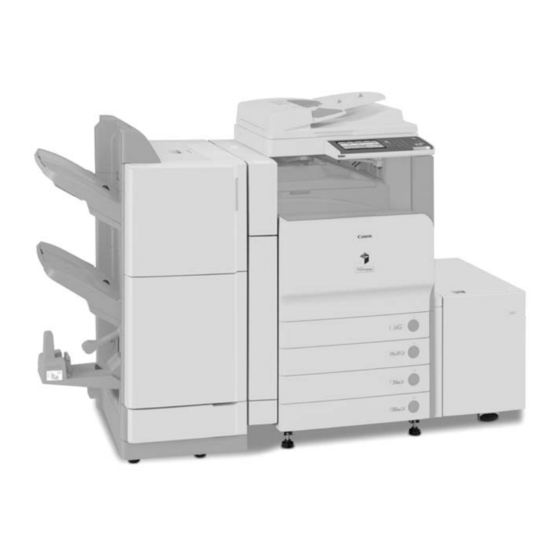
1.1 System Construction
Overview of system configurations and delivery accessories.
1.2 Product Specifications
Details on machine specifications, including parts, usage, and safety.
Chapter 2 Installation
2.1 Making Pre-Checks
Crucial steps before installing the machine, including site selection and compatibility.
2.2 Unpacking and Installation
Step-by-step guide for unboxing and installing the main machine components.
2.3 Checking the Connection to the Network
Verifying network connectivity is essential for functions like sending and remote access.
2.4 Troubleshooting the Network
Guidance for resolving network connection issues, including checks for common problems.
2.5 Checking the Images/Operations
Verifying the machine's functionality and image quality after installation.
2.7 Installing the Copy Tray
Procedure for installing the optional copy tray accessory.
2.8 Installing the Card Reader
Step-by-step guide for installing the card reader accessory.
2.10 Installing the Key Switch Unit
Procedure for installing the key switch unit accessory.
2.11 Installing the Voice Guidance Kit
Step-by-step guide for installing the voice guidance kit accessory.
2.13 Installing the Wireless Network Interface Adapter
Step-by-step guide for installing the wireless network interface adapter.
2.14 Installing the DADF
Procedure for installing the duplex automatic document feeder (DADF).
2.15 Installing the Inner 2 Way Tray
Step-by-step guide for installing the optional inner 2 way tray.
Chapter 3 Basic Operation
3.1 Construction
Overview of the machine's functional system blocks and their interconnections.
3.2 Basic Sequence
Describes the power-on sequence and basic operations for print jobs.
Chapter 4 Main Controller
4.1 Construction
Details the main controller block's components and their functions.
4.2 Construction of the Electrical Circuitry
Details the major control functions of the main controller PCB grouped by jack/IC.
4.3 Start-Up Sequence
Explains the sequence of operations when the machine is started up.
4.4 Actions when HDD Error
Provides detailed information and remedial actions for HDD errors.
4.5 Image Processing
Describes the flow of image data through various processing stages.
4.6 Flow of Image Data
Illustrates image data flow for different functions like copier, box, SEND, and fax.
4.7 Parts Replacement Procedure
Detailed procedures for replacing major components of the main controller.
Chapter 5 Original Exposure System
5.1 Construction
Details specifications, control mechanisms, and functions of the original exposure system.
5.2 Basic Sequence
Describes the operational sequence during power-on and when the start key is pressed.
5.3 Various Control Mechanisms
Explains controls for the scanner drive system, motor, and sensors.
5.4 Parts Replacement Procedure
Procedures for replacing components like copyboard glass and reader controller PCB.
Chapter 6 Laser Exposure
6.1 Construction
Details specifications, control mechanisms, and functions of the laser exposure system.
6.2 Various Control
Explains various controls related to laser activation timing and intensity.
6.3 Parts Replacement Procedure
Procedures for replacing the laser scanner unit.
Chapter 7 Image Formation
7.1 Construction
Details specifications, control mechanisms, and functions of the image formation system.
7.2 Driving and Controlling the High-Voltage System
Explains the generation of various bias voltages for image formation.
7.3 Image Stabilization Control
Mechanisms used to ensure image quality against environmental or machine changes.
7.4 Special Control
Describes special controls like black band and color band sequences.
7.5 Drum Unit
Details the drum unit's components and detection mechanisms.
7.6 Toner Container
Information on toner supply, detection, and container management.
7.7 Transfer Unit
Outline of the transfer assembly and its blocks.
7.9 Parts Replacement Procedure
Procedures for replacing components like the process unit and drum unit.
Chapter 8 Pickup/Feeding System
8.1 Construction
Details specifications, controls, functions, and component arrangements of the pickup/feeding system.
8.2 Basic Sequence
Describes the basic sequence of operations for paper pickup and feeding.
8.3 Controlling the Feeding Speed
Explains how the machine adjusts paper feeding speed based on media type and resolution.
8.4 Detecting Jams
Details different types of paper jams and their detection mechanisms.
8.5 Cassette Pick-Up Unit
Overview and operational sequence of the cassette pickup unit.
8.6 Manual Feed Pickup Unit
Overview and operational sequence for the manual feed pickup unit.
8.7 Registration Unit
Details the overview and control mechanisms of the registration unit.
8.8 Pre-Fixing Feeding
Explains the fixing arch control related to paper feeding before the fixing process.
8.9 Duplex Feeding Unit
Overview of the duplex feeding unit and its operational sequences.
8.10 Delivery
Details delivery control and operations when mounting delivery accessories.
8.11 Parts Replacement Procedure
Procedures for replacing various components of the pickup/feeding system.
Chapter 9 Fixing System
9.1 Construction
Details specifications, controls, functions, and major components of the fixing system.
9.2 Various Control Mechanisms
Explains controls for fixing temperature and down sequence operations.
9.3 Film Unit Pressurizing Mechanism
Details the pressure and release control for the fixing film unit.
9.4 Protective Functions
Describes functions that detect overheating and cut power to the heater.
9.5 Parts Replacement Procedure
Procedures for replacing parts of the fixing system like the fixing unit and film unit.
Chapter 10 Externals and Controls
10.1 Control Panel
Overview of the control panel's components and functions like LCD, contrast, and touch switch.
10.2 Counters
Information on counters indicating output counts according to printer types.
10.3 Fans
Details the fans mounted on the machine for cooling.
10.4 Power Supply
Describes the routes of power supply inside the printer and to various options.
10.5 Parts Replacement Procedure
Step-by-step procedures for replacing external covers and internal components.
Chapter 11 MEAP
11.1 MEAP
Information on checking operating environment and setting up MEAP applications.
11.1.1 Checking the Operating Environment
Lists the requirements for the operating environment for MEAP maintenance.
11.1.2 Setting Up the Network
Procedure for allowing MEAP device to access network resources via SMS.
11.1.3 Setting the method to login to SMS
Describes how to change login services for MEAP device authentication.
11.1.4 Login to SMS
Procedure for logging into SMS using password or RLS authentication.
11.1.5 Checking Application List
How to view and check the status of installed MEAP applications.
11.1.6 Starting and Stopping a MEAP Application
Instructions for managing MEAP applications, including starting and stopping.
11.1.7 Checking the Platform Information
How to check MEAP versions and related software on the device.
11.1.8 MEAP Specifications
Details on MEAP specifications and compatibility requirements.
11.1.11 Installing an Application
Step-by-step guide for installing a MEAP application.
11.1.14 Adding a License File
Procedure for adding a license file to MEAP applications.
11.1.15 Disabling a License File (suspending a license)
Procedure for suspending or invalidating a MEAP application license.
11.1.16 Downloading/Removing an Invalidated License File
How to download or delete invalidated license files.
11.1.19 Uninstalling an Application
Procedure for uninstalling a MEAP application.
11.1.20 Changing Login Services
How to change MEAP device login services (Default, SDL, SSO).
11.1.21 Initializing the Password
Procedure for initializing the MEAP device password.
11.1.22 Creating a Backup for MEAP Application Area, Formatting the Hard Disk, Restoring the MEAP Application Area with the Backup, Using the SST (Service Support Tool)
Procedures for backing up, formatting, and restoring MEAP application data using SST.
11.1.23 Replacing the Hard Disk Drive
Procedure for replacing the hard disk drive in the MEAP device.
11.1.24 MEAP Safe Mode
How to start the system in safe mode to troubleshoot issues.
11.1.25 Setting HTTP port for MEAP application (level 2)
Configuration for setting the HTTP port for MEAP applications.
Chapter 12 RDS
12.1 RDS
Information on RDS application operation, service center setup, and communication tests.
12.1.1 Application operation mode
Describes the OFF/ON settings for e-RDS operation.
12.1.2 Service Center URL and Port Specification
Allows specifying the URL and port number for equipment information destination.
12.1.3 Communication test
Enables distinguishing communication status with UGW by executing a communication test.
12.1.4 Communication log
Provides a list of communication errors for troubleshooting.
12.1.5 Detailed Communication log
Displays detailed information of errors found in the communication log.
12.1.6 SOAP communication function
Explains processing achieved by SOAP communication for SSL client communication.
12.1.7 Resend at SOAP transmission error
Describes how e-RDS resends data that failed transmission due to SOAP errors.
12.1.8 e-RDS setting screen
Details the e-RDS settings within the service mode screen.
12.1.9 Sleep operation
Explains how e-RDS operates during sleep mode.
12.1.10 Network Setting (Maintenance)
Procedures for network configuration and maintenance.
12.1.11 e-RDS Setting (Maintenance)
Procedures for e-RDS configuration and maintenance.
12.1.12 Trouble shoot
Troubleshooting steps for common RDS issues.
12.1.13 Error message
Reference for error messages related to RDS.
Chapter 13 Maintenance and Inspection
13.1 Periodically Replaced Parts
Information on parts that require periodic replacement for optimal performance.
13.2 Durables and Consumables
Details on parts that may require replacement due to deterioration or damage.
13.3 Scheduled Servicing Basic Procedure
Guidance on performing scheduled maintenance tasks for reader and printer units.
Chapter 14 Standards and Adjustments
14.1 Scanning System
Procedures for adjustments after replacing CIS, copyboard glass, or reader controller PCB.
14.2 Laser Exposure System
Procedure for adjustments after replacing the laser scanner unit.
14.3 Image Formation System
Procedure for adjustments after replacing the secondary transfer roller.
14.4 Fixing System
Procedure for confirming the nip width of the fixing system.
14.5 Electrical Components
Procedures for adjustments after replacing major electrical components.
14.6 Pickup/Feeding System
Adjustments for horizontal registration related to pickup and manual feed.
Chapter 15 Correcting Faulty Images
15.1 Making Initial Checks
Initial checks to perform before troubleshooting image faults.
15.2 Test Print
Overview and selection of various test print types for identifying image faults.
15.3 Troubleshooting
Comprehensive guide to troubleshooting various machine malfunctions and errors.
Chapter 16 Self Diagnosis
16.1 Error Code Table
A comprehensive table listing error codes, their causes, and corrective actions.
16.2 Error Code Details
Detailed explanations of specific error codes and their troubleshooting steps.
16.3 Error Codes (SEND)
Error codes specifically related to the SEND function.
16.4 Jam Codes
Listings of jam codes for printer, finisher, and ADF related issues.
16.5 Alarm Codes
Listings of alarm codes and their corresponding descriptions.
Chapter 17 Service Mode
17.1 Outline
Introduction to the service mode structure and navigation.
17.2 DISPLAY (Status Display Mode)
Information on accessing and viewing status displays for COPIER and FEEDER.
17.3 I/O (I/O Display Mode)
Details on accessing and interpreting I/O signals for various machine components.
17.4 ADJUST (Adjustment Mode)
Procedures for adjusting various machine parameters like scanner and paper path.
17.5 FUNCTION (Operation/Inspection Mode)
Procedures for operating and inspecting machine functions.
17.6 OPTION (Machine Settings Mode)
Settings for optional equipment like sorters and boards.
17.7 TEST (Test Print Mode)
Procedures for performing various test prints to check machine performance.
17.8 COUNTER (Counter Mode)
Information on accessing and clearing various machine counters.
Chapter 18 Upgrading
18.1 Outline
Overview of system software types, upgrading process, and important notes.
18.2 Making Preparations
Steps for preparing the system software installation from CD or USB.
18.3 Formatting the HDD
Procedures for formatting all or selected partitions on the hard disk drive.
18.4 Downloading System Software
Guides for batch and single downloads of system software.
18.5 Uploading and Downloading Backup Data
Procedures for backing up and restoring MEAP application data.
18.6 Version Upgrade using USB
Instructions for upgrading system software via USB.
Chapter 19 Service Tools
19.1 Service Tools
Lists of special tools and solvents/oils required for servicing the machine.
Table of Contents
Save PDF
Print
Rename the bookmark
Delete bookmark?
Delete from my manuals?
Login
Sign In
OR
Sign in with Facebook
Sign in with Google
Upload manual
Upload from disk
Upload from URL
Need help?
Do you have a question about the Color iR C2550i and is the answer not in the manual?
Questions and answers