Table of Contents
Advertisement
User Manual
Installation
Industrial Ethernet Ruggedized Switch
MACH 1040 Family Full Gigabit
1
MAR1040
FAULT
USB
V.24
RM
Sb
R1
R2
P
2
MAR1040
1
MAR1040
FAULT
USB
V.24
RM
Sb
R1
R2
P
2
MAR1042
1
MAR1140
FAULT
USB
V.24
RM
Sb
R1
R2
P
2
MAR1140
1
MAR1142
FAULT
USB
V.24
RM
Sb
R1
R2
P
2
MAR1142
MAR1140, MAR1142
Installation MACH 1040
Release 04 10/2015
3
5
7
4
6
8
P
3
5
7
4
6
8
3
5
7
4
6
8
P
3
5
7
4
6
8
9
11
13
15
10
12
14
16
9
11
13
15
10
12
14
16
9
11
13
15
10
12
14
16
9
11
13
15
10
12
14
16
P
RM Stand by
1
3
5
R1 R2
FAULT
2
4
6
https://hirschmann-support.belden.eu.com
Relay
P2
R2
Relay
P1
R1
Relay
P2
R2
Relay
P1
R1
7
9
11
13
15
8
10
12
14
16
ETHERNET Service Port
Technical Support
Advertisement
Table of Contents

Related Manuals for Hirschmann MAR1040


Summarization of Contents
Safety Instructions
General Safety Guidelines
General guidelines for safe operation, handling, and maintenance of the device, including reading documentation before use.
Intended Usage
Specifies the approved applications and adherence to technical specifications for the product.
Installation Site Requirements
Guidelines for selecting a suitable installation location and mounting the device safely.
Device Casing and Personnel Safety
Device Casing Precautions
Instructions regarding accessing and interacting with the device's casing and its ventilation.
Qualified Personnel Requirements
Details the necessary training and characteristics for personnel working on the device.
National and International Safety Regulations
Emphasizes verifying compliance with applicable electrical installation safety regulations.
Grounding and Power Supply Safety
Device Grounding Procedures
Procedures and requirements for properly grounding the device for safety.
Shielded Ground Connection
Explains the connection of shielded ground wires and potential short circuit risks.
Supply Voltage Connection Requirements
Details requirements for connecting the supply voltage, including isolation and fuses.
Hazardous Location Usage Guidelines
Use in Hazardous Locations (Class 1, Division 2)
Specifies suitability for hazardous locations and associated conditions like temperature and enclosure requirements.
Regulatory Compliance and Component Information
CE Marking Compliance
Lists EU directives (RoHS, EMC, Low Voltage) the labeled devices comply with.
LED and Laser Component Classification
Classifies LED and laser components according to IEC standards.
FCC Compliance Note
Details FCC compliance rules and potential interference issues in residential areas.
Device Recycling Instructions
Instructions for proper disposal of the device as electronic waste.
About This Manual and Legend
Manual Overview
Describes the content of the installation manual and available supporting documents.
Symbol Legend
Explains the meaning of symbols used throughout the manual for clarity.
1 Description of the MACH 1040 Switch
1.1 General Device Description
Overview of the MACH 1040's features, industrial automation focus, and connectivity options.
1.2 Combination Options for Device Variants
Explains how to combine device characteristics to form product designations and lists variants.
1.3 Description of Device Variants
Details the features of different MACH 1040 variants like port types and PoE support.
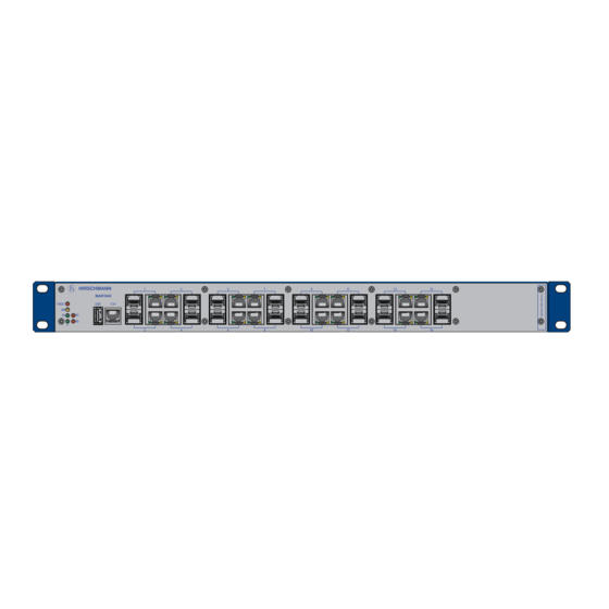
1.3.1 MAR1040-... with 16 Gigabit Ports
Illustrates the MAR1040 device, its front and back panel connections.
1.3.2 MAR1042-... with 16 Gigabit Ports and PoE
Shows the MAR1042 device, detailing its front and back panel connections including PoE.
1.3.3 MAR1040-... with Ports on Back
Depicts the MAR1140 device with ports on the back and front diagnostic port.
1.3.4 MAR1142-... with Ports on Back and PoE
Illustrates the MAR1142 with rear ports, front diagnostic port, and PoE capabilities.
1.3.5 Power over Ethernet (PoE) Support
Explains PoE support in MAR1042/MAR1142, its standards, and power output.
1.4 Gigabit Combo Port Details
Describes the 16 combo ports for transmission speeds up to 1000 Mbit/s.
1.4.1 10/100/1000 Mbit/s Twisted Pair Port
Describes the RJ45 socket port, its capabilities, and support for PoE.
1.4.2 100/1000 Mbit/s Fiber Optic Port
Details the SFP slot port for fiber optic connections and its supported speeds.
1.4.3 Pin Assignments
Provides pin assignments for RJ45 and M12 connectors for data and PoE connections.
1.5 Device Display Elements
1.5 Display Elements Overview
Introduces device status LEDs and port status LEDs for MAR1040/MAR1042.
1.5.1 Device State - Power Supply
Details the 'P' LED for supply voltage status on devices with one or two power supply units.
1.5.1 Device State - System LEDs
Explains device status LEDs like Stand-by, RM, FAULT, R1, and R2.
1.5.1 Device State - Signal Contact
Covers R1/R2 signal contact behavior and manual adjustment settings.
1.5.2 Port State Indicators
Describes port status LEDs indicating link status and data activity.
1.6 Management Interfaces
1.6.1 V.24 Interface (External Management)
Describes the V.24 serial interface for CLI management and VT100 terminal settings.
1.6.2 USB Interface
Explains the USB interface for AutoConfiguration Adapter ACA21 and its uses.
1.7 Signal Contact Functionality
Signal Contact Operation
Explains the potential-free relay signal contact, its functions, and events triggering it.
2 Installation Procedures
2.1 Checking Package Contents
Procedures to verify all items are present and check for transport damage.
2.2 Installing an SFP Transceiver
Step-by-step guide for inserting an SFP transceiver into its slot.
2.3 Connecting Power and Signal
2.3.1 Connecting the Supply Voltage
Instructions and warnings for connecting the device's supply voltage, including type M and L.
2.3.2 Connecting the Signal Contact
Steps and requirements for connecting signal contact wires to the terminal block.
2.4 Device Installation and Grounding
2.4.1 Mounting in a Switch Cabinet
Guidelines for installing the device in a 19" switch cabinet using rails.
2.4.2 Vertical Mounting on the Wall
Instructions for mounting the device vertically on a wall, including fire hazard warnings.
2.4.3 Grounding the Device
Specifies grounding the device via the dedicated screw on the back.
2.5 Device Operation and Data Cables
2.5 Operating the Device
Brief instruction on device startup upon connecting supply voltage.
2.6 Connecting Data Cables
General recommendations for connecting data cables to device ports.
2.6.1 Twisted Pair Ports
Recommendations for connecting twisted pair cables in environments with high electrical interference.
2.6.2 Optical Fiber Ports
Instructions for connecting optical fiber cables, ensuring correct port types are used.
3 Basic Settings Configuration
Making Basic Settings
Options for configuring IP addresses and default management settings.
4 Ambient Air Temperature Monitoring
Monitoring Ambient Air Temperature
Guidance on operating within specified ambient air temperature limits and understanding internal vs. ambient temps.
5 Maintenance and Service
Maintenance and Service Procedures
Information on device longevity, relay wear, software updates, and cleaning ventilation slots.
6 Device Disassembly
6.1 Removing the Device
Steps to safely detach the device from its mounting, including disconnecting cables and power.
6.2 Removing an SFP Transceiver
Procedure for safely removing an SFP transceiver from its slot.
7 Technical Data
General Technical Specifications
Key specifications including dimensions, weight, power supply types, and signal contact parameters.
Climatic and Environmental Conditions
Details clearance, temperature, humidity, and air pressure during operation and storage.
Protection Ratings
Specifies pollution degree rating and protection class for laser/general components.
Dimension Drawings
Dimensions for Flat Surface Mounting
Visual representation of the device's physical dimensions for flat surface mounting.
Dimensions for Switch Cabinet Mounting
Illustrates the device's dimensions specifically for switch cabinet installation.
EMC and Immunity Standards
EMC Interference and Immunity Tests
Lists EMC interference and immunity test levels according to IEC/EN and IEEE standards.
EMC Emission and Environmental Tests
Details emission standards (EN 55022, FCC) and environmental tests.
Network Transceiver Range and Power
Network Transceiver Range Specifications
Specifies line lengths for transceivers based on fiber type, attenuation, and dispersion.
Power Consumption and Output Details
Details power consumption and output for device variants with and without PoE.
Scope of Delivery and Accessories
Scope of Delivery Contents
Lists included package items and order numbers for device variants.
Recommended Accessories List
Lists recommended SFP transceivers and other accessories with their order numbers.
Fast Ethernet SFP Transceiver Options
Lists Fast Ethernet SFP transceivers and their operating conditions.
Other Essential Accessories
Lists additional accessories like adapters, cables, and software with order numbers.
Underlying Technical Standards
List of Underlying Technical Standards
Lists underlying technical standards (EN, FCC, UL, IEEE) relevant to the device.
A Further Support Information
Technical Support Contacts
Provides contact information for technical questions and details about the Hirschmann Competence Center.
Need help?
Do you have a question about the MAR1040 and is the answer not in the manual?
Questions and answers