
Related Manuals for SCHUNK ROTA NCO 400


Summary of Contents for SCHUNK ROTA NCO 400
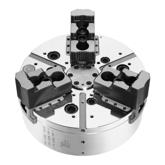
- Page 1 Translation of the original operating manual Power Chuck ROTA NCO Operating Manual Superior Clamping and Gripping...
- Page 2 Imprint Copyright: This manual remains the copyrighted property of SCHUNK GmbH & Co. KG. It is solely supplied to our customers and operators of our products and forms part of the product. This documentation may not be duplicated or made accessible to third parties, in particu- lar competitive companies, without our prior permission.
-
Page 3: Table Of Contents
Table of contents Table of contents 1 General ........................5 1.1 Warnings ........................5 1.2 Applicable documents ....................6 2 Basic safety notes ..................... 7 2.1 Intended use ......................7 2.2 Not intended use ...................... 7 2.3 Notes on particular risks ................... 8 2.4 Notes on safe operation .................. - Page 4 Table of contents 9 Maintenance ......................34 9.1 Lubrication ......................34 9.2 Maintenance intervals .................... 34 9.3 Central oil lubrication ..................... 35 9.4 Changing the top jaws .................... 35 10 Disposal ........................35 11 Spare parts ......................36 12 Assembly drawings ....................38 13 Translation of original EC declaration of incorporation ..........
-
Page 5: General
General General This operating manual is an integral component of the product and contains important information on safe and proper assembly, commissioning, operation, care, maintenance and disposal. This manual must be stored in the immediate vicinity of the product where it is accessible to all users at all times. Before using the product, read and comply with this manual, especially the chapter “Basic safety notes”.(... -
Page 6: Applicable Documents
Warning about hot surfaces Applicable documents General terms of business Catalog data sheet of the purchased product Calculation of the jaw centrifugal forces ("Technology" chapter in the lathe chuck catalog) The above mentioned documents can be downloaded at www.de.schunk.com. 01.04| ROTA NCO |en... -
Page 7: Basic Safety Notes
Report any failures and damage immediately and repair without delay to keep the extent of the damage to a minimum and prevent compromising the safety of the product. Only use original SCHUNK spare parts. Intended use The chuck is used to clamp workpieces on machine tools and other suitable technical facilities, paying particular attention to the technical data specified by the manufacturer. -
Page 8: Notes On Particular Risks
Basic safety notes • The technical data for use of the product specified by the man- ufacturer are exceeded. Notes on particular risks This product may pose a danger to persons and property if, for example: • It is not used as intended; •... - Page 9 Basic safety notes DANGER Possible risk of fatal injury to operating personnel if a jaw breaks or if the chuck fails because the technical data have been exceeded and a workpiece is released or parts fly off! • The technical data specified by the manufacturer for using the chuck must never be exceeded.
- Page 10 Basic safety notes CAUTION Danger of slipping and falling in case of dirty environment where the chuck is used (e.g. by cooling lubricants or oil). • Make sure the work environment is clean before beginning assembly and installation tasks. • Wear suitable safety shoes. •...
-
Page 11: Notes On Safe Operation
Basic safety notes CAUTION Hazard from vibration due to imbalanced rotating parts and noise generation. Physical and mental strains due to imbalanced workpieces and noise during the machining process on the clamped and rotating workpiece. • Ensure the chuck's axial and concentric runout. •... - Page 12 (clamping force, coefficient of friction, wear characteristics). (For product information about LINO MAX, see the "Accessories" chapter of the SCHUNK lathe chuck catalog or contact SCHUNK). • Use a suitable high-pressure grease gun to ensure that you reach all the greasing areas.
- Page 13 Basic safety notes The operating clamping force must in this case be determined by means of dynamic measurement. • Move the clamping piston through to its end position several times after 500 clamping strokes, at the latest. (This moves the lubricant back to the surfaces of the force transmission.
-
Page 14: Substantial Modifications
• If the chuck is involved in a collision, it must be subjected to a crack test before using it again. Replace damaged parts with original SCHUNK spare parts. • Replace the chuck jaw mounting screws if there are signs of wear or damage. -
Page 15: Using Personal Protective Equipment
Only allow specialists to remedy faults. Spare parts Only ever use original SCHUNK spare parts. Environmental regulations Comply with the applicable legal norms when disposing of waste. -
Page 16: Warranty
Warranty Warranty If the product is used as intended, the warranty is valid for 24 months from the date of delivery from the production facility under the following conditions: • Observe the applicable documents( 1.2, Page 6) • Observe the environmental and operating conditions. •... -
Page 17: Torque Per Screw
Torque per screw / Scope of delivery Torque per screw Tightening torques for mounting screws for clamping the chuck (screw quality 10.9) Screw size M6 M8 M10 M12 M14 M16 M18 M20 M22 M24 M27 M30 Admissible torque 120 160 200 290 400 500 1050 1500 (Nm) Tightening torques to mount top jaws onto the chuck (screw quality 12.9) -
Page 18: Technical Data
Technical data Technical data Chuck data ROTA NCR Max. actuating force [kN] Max. clamping force [kN] Max. rotation speed [min-1] 6000 5000 4500 3600 2500 2000 1600 Stroke per jaw [mm] 10.0 13.0 15.0 15.0 15.0 Piston stroke [mm] Centrifugal torque of base jaw 0.025 0.043 0.099 0.161 0.431 0.674 1.085 fine serration [kgm]... - Page 19 Technical data The chuck is in perfect condition and lubricated with SCHUNK LINO MAX special grease. Should one or several of the above mentioned parameters be changed the diagrams are no longer valid. Chuck set-up for clamping force / speed diagram...
- Page 20 Technical data Clamping force / speed diagram ROTA NCO 210 Clamping force / speed diagram ROTA NCO 260 Clamping force / speed diagram ROTA NCO 315 01.04| ROTA NCO |en...
- Page 21 Technical data Clamping force / speed diagram ROTA NCO 400 Clamping force / speed diagram ROTA NCO 500 Clamping force / speed diagrams ROTA NCO 630 01.04| ROTA NCO |en...
-
Page 22: Calculations For Clamping Force And Speed
Technical data Calculations for clamping force and speed Missing information or specifications can be requested from the manufacturer! Legend Total centrifugal force [N] Centrifugal torque of top jaws [Kgm] Effective clamping force [N] Centrifugal torque of base jaws [Kgm] Minimum required clamping force [N] n Speed [rpm] spmin Initial clamping force [N]... - Page 23 Technical data Reduction in effective clamping force by the magnitude of the total centrifugal force, for gripping from the outside inwards. The required effective clamping force for machining F is calculat- ed from the product of the machining force F with the safety factor S .
-
Page 24: Calculation Example: Required Initial Clamping Force Fsp0 For A Given Rpm N
Technical data NOTICE For safety reasons, in accordance with DIN EN 1550, the centrif- ugal force may be a maximum of 67% of the initial clamping force. The formula for the calculation of the total centrifugal force F n is the given speed in r.p.m. The product m ∙... -
Page 25: Calculation Example: Permissible Rpm For A Given Effective Clamping Force
Technical data First the required effective clamping force F is determined using the specific machining force: Initial clamping force during shutdown: Calculation of total centrifugal force: For two-part chuck jaws, the following is valid: The centrifugal torques of the base jaw and the top jaw are taken from the table “Chuck data”: For centrifugal torque of the top jaw, the following is valid: Centrifugal torque for one jaw:... -
Page 26: Grades Of Accuracy
Technical data Calculation example: permissible RPM for a given effective clamping force The following data is known from previous calculations: • Initial clamping force when not rotating F = 17723 N • Machining force for machining job F 3000 N (application- specific) •... -
Page 27: Mounting
Mounting Mounting Pre-assembly measures Carefully lift the product (e.g. using suitable lifting gear) from the packaging. CAUTION Danger of injury due to sharp edges and rough or slippery surfaces Use personal protective gear, especially safety gloves. Check the delivery for completeness and for transport damage. Mounting of the Power Chuck •... -
Page 28: Horizontal Attachment
Lift the chuck by means of an assembly belt or with a ring bolt aligned to the spindle centre in front of the spindle nose. • ROTA NCO 165: Screw the chuck on to the spindle by turning it on its axis until it stops. -
Page 29: Function
Function Function The item numbers specified for the corresponding individual components relate to chapter drawings.( 12, Page 38) Function and handling Wedge hook chuck are actuated by rotating cylinders with or without through holes. The axial draw- or pressure forces are deviated into a radial jaw clamping force via the helical angle of traction between the piston and the base jaws. - Page 30 Function • Remove the top jaws (if existing), T-nuts and fastening screws from the base jaws. • Screw screws (item 73) out of the chuck and take out media insert (item 24). Set screw (item 28) can be taken out (insert without media lead-through only).
-
Page 31: Assembly Of Various Energy Inserts
Degrease and clean all parts and check them for damage or wear. Before installation, lubricate parts well with LINO MAX special grease. Only use original SCHUNK spare parts when exchanging damaged parts. The chuck is assembled in the same way but in the reverse order. - Page 32 Function Modification – Central lubrication Modification – Air control 01.04| ROTA NCO |en...
- Page 33 Function Modification – Coolant 01.04| ROTA NCO |en...
-
Page 34: Maintenance
If the clamping force has dropped down too low, or if the base jaws and piston cannot be freely moved any more, the chuck has to be disassembled, cleaned and lubricate again. Only use SCHUNK original spares when replacing damaged parts. Maintenance intervals Lubrication of the grease areas:... -
Page 35: Central Oil Lubrication
• Dispose of the chuck's metal parts as scrap metal. Alternatively, you can return the chuck to SCHUNK for proper disposal. 01.04| ROTA NCO |en... -
Page 36: Spare Parts
Spare parts Spare parts When ordering spare parts, it is imperative to specify the type, size and above all the manufacturing no of the chuck. Seals, sealing elements, screw connections, springs, bearings, screws and wiper bars plus parts coming into contact with the workpiece are not covered by the warranty. - Page 37 O-ring DIN 3771 O-ring DIN 3771 Set screw DIN EN ISO 4027 Set screw DIN EN ISO 4027 Modifications(chapter 8.4) ** Not use for ROTA NCO 165 Plug O-ring DIN 3771 Internal valve components Scuring ring DIN 472 Gauge cartridge...
-
Page 38: Assembly Drawings
Assembly drawings Assembly drawings ROTA NCO 165 – 400 At modification oil central lubrication Not use for NCO 165, Item 8 is screwed with Item 4 2 x for NCO 165 01.04| ROTA NCO |en... - Page 39 Assembly drawings ROTA NCO 500 – 630 01.04| ROTA NCO |en...
-
Page 40: Translation Of Original Ec Declaration Of Incorporation
Product Power Chucks without through hole designation: ROTA NCO 165; 210; 260; 315; 400; 500; 630; 800; 1000 0856000; 0856001; 0856002; 0856003; 0856010; 0856011; 0856012; 0856013; ID number 0856014; 0856015; 0856020; 0856021; 0856022; 0856023; 0856024; 0856025;...
Need help?
Do you have a question about the ROTA NCO 400 and is the answer not in the manual?
Questions and answers