
Related Manuals for Satec PM135EH


Summarization of Contents
Chapter 1 General Information
1.1 Product Features
Details the multifunctional capabilities of the PM135 Power Meter.
1.2 Available Options
Lists optional expansion modules for the PM135, such as Digital I/O and Analog Outputs.
1.4 Measured Parameters
Lists and categorizes the parameters measured and displayed by the PM135.
Chapter 2 Installation
2.1 Site Requirements
Specifies environmental and electrical conditions required for installation.
2.2 Package Contents
Lists the items included in the PM135 Powermeter package.
2.3 Mechanical Installation
Provides instructions and diagrams for physically mounting the PM135 unit.
2.4 Electrical Installation
Details the electrical wiring and connection procedures for the PM135.
2.5 I/O Connections
Explains how to connect Digital I/O modules and their functions.
2.6 Communications Connections
Describes available communication options like RS-485, Ethernet, GPRS, and PROFIBUS.
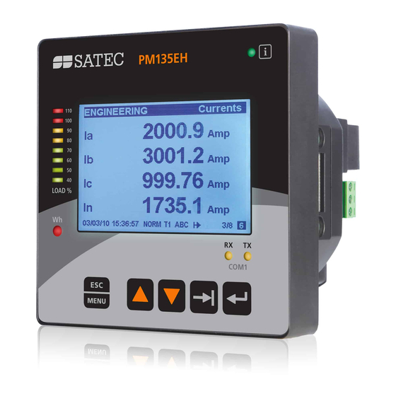
Chapter 3 Using Front Display
3.1 Display Operations
Explains how to navigate and use the PM135's front panel display and its modes.
3.2 Data Displays
Lists and describes the various multi-page data displays available on the PM135.
Chapter 4 Using PAS Software
4.1 Installing PAS Software
Step-by-step guide for installing the PAS configuration and data acquisition software.
4.2 Creating a New Site
Instructions on creating a site database within PAS for meter configuration.
4.3 Setting up Communications
Details on configuring communication settings for the PM135 via serial port or internet.
4.4 Setting Up the Meter
Guide on preparing and downloading meter setups using the PAS software.
Chapter 5 Configuring the PM135
5.1 Configuring Communications
Explains how to configure serial communication ports and network setups.
5.2 General Meter Setup
Details basic configuration settings including wiring mode, PT/CT ratios, and frequency.
5.3 Configuring Meter Security
Covers changing user passwords and enabling/disabling password protection.
5.4 Configuring Billing/TOU
Explains configuration of Time-of-Use (TOU) billing, energy registers, and tariff rates.
5.5 Configuring Recorders
Details how to configure meter memory for data and event recording.
5.6 Configuring Communication Protocols
Describes how to customize protocol options for Modbus, DNP3, and other protocols.
Chapter 6 Device Control and Upgrading
6.1 Resetting Data and Files
Instructions for clearing meter data, demands, counters, and diagnostics.
6.2 Viewing and Clearing Diagnostics
How to view and clear device diagnostic messages and events.
6.3 Viewing Communication Status
Information on checking and clearing communication status and counters.
6.4 Remote Relay Control
How to send remote commands to operate or release relays.
6.5 Upgrading Device Firmware
Step-by-step guide for downloading and upgrading the meter's firmware via PAS.
Chapter 7 Monitoring Meters
7.1 Viewing Real-time Data
How to retrieve and view live measurement data from the meter using PAS.
7.2 Viewing Real-time Min/Max Log
Procedures for retrieving and viewing minimum and maximum recorded data logs.
7.3 Viewing Real-time Waveforms
How to retrieve and display voltage and current waveforms in real-time.
7.4 Viewing Real-time Harmonic Spectrum
Guide to viewing real-time harmonic spectrum data for voltage and current.
Chapter 8 Retrieving and Storing Files
8.1 Uploading Files on Demand
Instructions for manually retrieving log files from the meter to PC.
8.2 Using the Upload Scheduler
Setting up automated data retrieval schedules for meters.
8.3 Viewing Files On-line
How to view historical data directly from the meter without storing it.
8.4 Exporting Files
Procedures for exporting data files in COMTRADE, PQDIF, and Excel formats.
8.5 Archiving Files
Setting up schedules to automatically archive older data files.
Chapter 9 Viewing Files
9.1 Operations with Files
Basic operations for opening and saving database tables and files.
9.2 Viewing Options
Options for customizing views, including date order, font, and grid.
9.3 Viewing the Event Log
How to view and filter the event log, which contains configuration changes and diagnostics.
9.4 Viewing the Data Log
Viewing data log files in tabular or trend graph format.
Appendix A Technical Specifications
A.1 Environmental Conditions
Specifies operating and storage temperature, and humidity requirements.
A.2 Construction
Details materials, dimensions, and weight of the PM135 unit.
A.3 Power Supply Options
Lists available power supply options (VAC-DC) and their specifications.
A.4 Input Ratings
Specifies voltage and current input ratings, installation categories, and burdens.
A.6 Optional Digital Inputs
Technical specifications for optional digital input modules.
A.7 Optional Analog Outputs
Technical specifications for optional analog output modules.
A.8 Communication Ports
Details specifications for COM1 (RS-485) and COM2 (Ethernet, PROFIBUS, etc.) ports.
A.9 Real-time Clock
Specifications for the standard and TOU module real-time clocks.
A.10 Display Specifications
Describes the PM135's LCD display and status LEDs.
A.11 Standards Compliance
Lists compliance with various accuracy, immunity, emission, and safety standards.
A.12 Measurement Specifications
Detailed measurement accuracy and range specifications for various parameters.
Appendix B Analog Output Parameters
Analog Output Parameters List
Lists available parameters that can be outputted via the meter's analog outputs.
Appendix C Setpoint Triggers and Actions
Setpoint Triggers and Actions Overview
Lists available setpoint triggers, including digital inputs, phase reversal, and voltage/current readings.
Appendix D Parameters for Data Monitoring and Logging
Data Monitoring and Logging Parameters
Lists parameters available for monitoring and logging via communications and data logs.
Appendix E Billing/TOU Profile Log File
Billing/TOU Profile Log File Structure
Describes the record structure for the daily billing data profile log file.
Appendix F Data Scales
Data Scales Explanation
Explains how voltage, current, and power scales affect meter display and communication limits.
Appendix G Device Diagnostic Codes
Device Diagnostic Codes List
Lists device diagnostic codes, their messages, descriptions, and reasons.
Need help?
Do you have a question about the PM135EH and is the answer not in the manual?
Questions and answers