Advertisement
Table of Contents
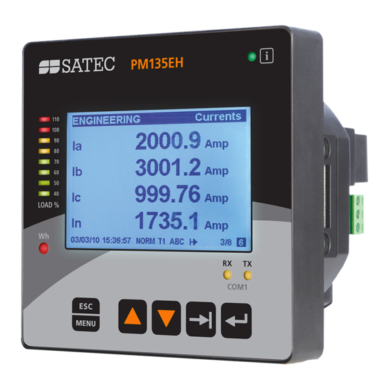
PM135 Quick Start Manual
This quick start manual is a short guide on how to mount, connect, configure and operate the
PM135. It is not intended to replace reading the full user manual and particularly the safety
precautions.
Mounting, electrical connection and settings of the PM135 shall be made in
accordance with all applicable laws and/or regulations and be performed by
authorized personnel only.
MOUNTING
Position the PM135 meter in 92×92mm square or 4" round cutout (Figure 1). If two PM135 are
positioned side by side, keep at least 150mm (5.9") between their centers to allow installation
of add-on modules (140mm/5.5" if only small form modules will be used).
Attach the PM135 unit using washers and nuts. Make sure that the unit is securely attached
into the wall or cabinet fixture.
Figure 1
BG0517 REV.A1 ENGLISH
PM135 QuickStart
Win a
Tablet!
See back page
www.satec-global.com
Advertisement
Table of Contents

Related Manuals for Satec PM135


Summary of Contents for Satec PM135
- Page 1 MOUNTING Position the PM135 meter in 92×92mm square or 4” round cutout (Figure 1). If two PM135 are positioned side by side, keep at least 150mm (5.9”) between their centers to allow installation of add-on modules (140mm/5.5” if only small form modules will be used).
- Page 2 10. Make sure the diagnostic led is off and solid “123” phase indication is displayed Figure 2 Figure 2C Figure Note The “optional CT wire termination” allows connection of the two wires from the CTs. They have no internal connection and their use is optional. PM135 QuickStart www.satec-global.com...
- Page 3 OPERATION The PM135 is operated using the front panel which consists of an LCD display, 12 LEDs and five keys as shown below: Diagnostic LED. Off = OK Title (displayed value, units, Load bar graph phase/s) (full load according to...
- Page 4 Select the value to be reset, press select, then press for 5 seconds until the "Do" notification is changed to "Done". For a Chance to Win a Tablet Register Your Product Here: WIN! www.satec-global.com/register Copyright © 2013 SATEC Ltd. PM135 QuickStart www.satec-global.com...
Need help?
Do you have a question about the PM135 and is the answer not in the manual?
Questions and answers