Table of Contents
Advertisement
Quick Links
Download this manual
See also:
User Manual
PX865PEC PRO(2.0)
Copyright
All rights are reserved. No part of this publication may be reproduced, transmitted, transcribed,
stored in a retrieval system or translated into any language or computer language, in any form or by
any means, electronic, mechanical, magnetic, optical, chemical, manual or otherwise, without the
prior written permission of the company. Brands and product names are trademarks or registered
trademarks of their respective companies.
The vendor makes no representations or warranties with respect to the contents herein and especially
disclaim any implied warranties of merchantability or fitness for any purpose. Further the vendor
reserves the right to revise this publication and to make changes to the contents herein without
obligation to notify any party beforehand. Duplication of this publication, in part or in whole, is not
allowed without first obtaining the vendor's approval in writing.
Disclaimer
We make no warranty of any kind with regard to the content of this user's manual. The content is
subject to change without notice and we will not be responsible for any mistakes found in this user's
manual. All the brand and product names are trademarks of their respective companies.
FCC Compliance Statement
This equipment has been tested and found to comply with the limits of a Class B digital device,
pursuant to Part 15 of the FCC Rules. These limits are designed to provide reasonable protection
against harmful interference in a residential installation. This equipment generates, uses and can
radiate radio frequency energy and, if not installed and used in accordance with the instructions, may
cause harmful interference to radio communications. Operation of this equipment in a residential area
is likely to cause harmful interference in which case the user will be required to correct the
interference at his own expense. However, there is no guarantee that interference will not occur in a
particular installation.
Ver: EG102
Advertisement
Table of Contents

Subscribe to Our Youtube Channel
Related Manuals for Albatron PX865PEC PRO(2.0)


Summary of Contents for Albatron PX865PEC PRO(2.0)
-
Page 1: Fcc Compliance Statement
PX865PEC PRO(2.0) Copyright All rights are reserved. No part of this publication may be reproduced, transmitted, transcribed, stored in a retrieval system or translated into any language or computer language, in any form or by any means, electronic, mechanical, magnetic, optical, chemical, manual or otherwise, without the prior written permission of the company. -
Page 2: Packing List
Do not touch the IC chips, leads, connectors or other components. Unplug the AC power when you install or remove any device on the mainboard. Packing List PX865PEC PRO(2.0) mainboard FDD Cable HDD Cable Rear I/O panel for ATX case S/PDIF &... - Page 3 PX865PEC PRO(2.0) Intel Supports Socket 478 Intel User Manual Enabling the Hyper-Threading Technology, your computer system is required as the following components: ® CPU: An Intel Pentium ® Chipset: An Intel Chipset that supports HT Technology BIOS: A BIOS that supports HT Technology and has it enabled...
-
Page 4: Table Of Contents
CHAPTER 1. GETTING STARTED ...1 ... 1 NTRODUCTION ... 2 PECIFICATION ... 5 ONFIGURATION Layout of PX865PEC PRO(2.0) ... 5 ... 6 ARDWARE NSTALLATION CPU Processor Installation ... 6 Memory Installation... 7 Back Panel Configuration ... 9 Front Panel Headers Indication ... 11 Connectors ... -
Page 5: Chapter 1. Getting Started
4GB. You can install unbuffered & non-ECC DDR400/ 333/ 266 (PC3200/ 2700/ 2100) SDRAM. The PX865PEC PRO(2.0) mainboard provides one x8 AGP Slot with AGP 3.0 specification and five 32-bit PCI Slots. The PX865PEC PRO(2.0) mainboard includes two built-in IDE facilities that support Ultra ATA 33/66/100 BMIDE and PIO Modes. -
Page 6: Specification
Specification CPU: Support Socket 478 Intel Support Hyper Threading Technology Chipset: Northbridge Chip (MCH) – Intel Southbridge Chip (ICH) – Intel I/O Controller – ITE IT8712F AC’97 Audio Codec – ALC655 LAN Controller – RTL8100C DRAM Memory: Support DDR400 (PC3200)/ 333 (PC2700)/ 266 (PC2100) SDRAM Support 64 MB/128 MB/256 MB/512 MB/1 GB unbuffered &... -
Page 7: Universal Serial Bus
AC’97 Sound Codec Onboard: High performance CODEC with high S/N ratio (>90 dB) Compliant with AC’97 2.3 specification Support 6-channel playback capability (Super 5.1 Channel Audio Effect) Support 3D Stereo enhancement Support Sony/ Philips Digital Interface (S/PDIF) function LAN Chip onboard: 10/100 Mbps Ethernet supported I/O facilities: One Multi-parallel Port capable of supporting the following specifications:... -
Page 8: Watch Dog Timer
Watch Dog Timer: This mainboard contains a special feature called the “Watch Dog Timer” which is used to detect when the system is unable to handle over-clocking configurations during the POST stage. Once a problem is detected the system will reset the configurations and reboot the system after five seconds. -
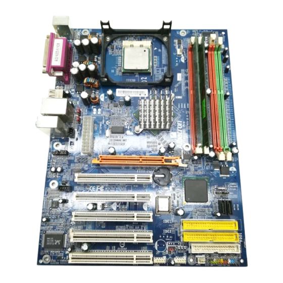
Page 9: Configuration
Configuration Layout of PX865PEC PRO(2.0) -
Page 10: Hardware Installation
Hardware Installation This section will assist you quickly in installing your system hardware. Wear a wrist ground strap before handling components. Electrostatic discharge may damage your system components. CPU Processor Installation ® This mainboard supports Intel Pentium system, we suggest you to visit the Intel website and review the processor installation procedures. http://www.intel.com CPU Socket 478 Configuration Steps: Locate the CPU socket on your mainboard and nudge the lever away from the socket. -
Page 11: Memory Installation
4 GB. You can install unbuffered & non-ECC DDR memories. When you installed a 100MHz clock speeds CPU, it can support DDR266. When you installed a 133MHz clock speeds CPU, it can support DDR266/333. And the PX865PEC PRO(2.0) also supports DDR266/320/400 when you installed a 200MHz clock speeds CPU. -
Page 12: Memory Modules Installation
To Enable Dual-Channel DDR, the following conditions must be met: 1.You must insert either DDRA1 & DDRA2 together or DDRB1 & DDRB2 together or all four memory modules together. 2.You must insert the same memory configurations between DDRA1 & DDRA2, and DDRB1 & DDRB2. -
Page 13: Back Panel Configuration
Lower the memory module into the socket and press firmly using both thumbs until the module snaps to place. epeat step 1, 2 & 3 for the remaining memory modules setting. * The pictures shown above are for reference only. Your mainboard configuration may vary with the pictures shown. -
Page 14: Audio Port Connectors
Parallel Interface Port: JPRNT1 The parallel port on your system has a 25-pin connector and is used to connect parallel printers and other devices which are able to support with The Serial Interface: COM1 This mainboard provides a serial port COM1 on the back panel, and is used to connect mice, modems and other peripheral devices. -
Page 15: Front Panel Headers Indication
Speaker-Out (Green) It is a standard audio port for connecting the speaker or headphone connectors. When the Super 5.1 Channel Audio driver installed and enabled, your front speaker function will be enabled with this port. In addition, if you enable the Super 5.1 Channel Audio Effect but using the Standard 2 chan el audio function, we suggest you to connect this port, so that the outputed sounds can be high fidelity. - Page 16 IRTX SPK (Speaker Connector) A front panel speaker can be connected to this header. When you reboot the computer, the speaker will sound a short “beep”. If there is something wr otherwise will sound “irregular beep” to warn you. HLED (Hard Drive LED Header) This header can be connected to an HLED o flicker during the hard drive disk (HDD) devices directly connected to the mainboard.
-
Page 17: Connectors
Connectors Floppy Drive Disk Connector: FDD1 The mainboard provides a standard floppy drive connector (FDC) that supports 360K, 720K, 1.2M, 1.44M and 2.88M floppy disks. This connector supports the floppy drive ribbon cables provided in the packaging. Hard Drive Disk Connectors: IDE1/ IDE2、SATA1/ SATA2 The mainboard has a 32-bit enhanced IDE Controller that supports Ultra ATA 33, Ultra ATA 66, Ultra ATA 100 and Ultra ATA 133. -
Page 18: Headers & Jumpers
Headers & Jumpers Front USB Headers: JUSB2/ JUSB3 This mainboard provides 4 USB ports and 2 USB headers on the mainboard which allowing you to use 4 additional USB ports. An optional USB bracket may be included with this product. The bracket is typical secured to the back side of your computer case and has standard USB ports that you can connect to external USB devices. - Page 19 Clear CMOS Jumper: JCMOS1 The “Clear CMOS” function is used when you cannot boot your system due to some CMOS problems, such as a password is forgotten. This jumper allows you to reset the CMOS configurations, and then reconfigure it. The following steps explain how to reset your CMOS configurations when you have forgotten your system password.
-
Page 20: Audio Connectors
Audio Connectors This mainboard provides three connectors as part of its audio Subsystem. CD-ROM Audio-In Header: JCDIN1 This header is used to connect to a CD-ROM / DVD audio cable. S/PDIF (Sony/Philips Digital Interface) Headers:SPDIF_IN1/OUT1 S/PDIF is a recent audio transfer file format, which provides high quality audio using optical fiber and digital signals. -
Page 21: Slots
Slots This mainboard provides one AGP slots and five PCI slots. These slots are designed for expansion cards used, in order to complement and enhance the functionality of the mainboard and your system. AGP (Accelerated Graphics Port) Slot: AGP1 The mainboard is equipped a x8 Accelerated Graphics Port (AGP) for working with an VGA card. PCI (Peripheral Component Interconnect) Slots: PCI1/2/3/4/5 This mainboard is equipped with five 32-bit PCI slots. -
Page 22: Power Supply Attachments
Power Supply Attachments ATX Power Connector: ATX_PWR、ATX_PWR2 This mainboard provides two ATX power connectors, one 20-pin connector and one 4-pin connector. Through these connectors to supply the power, the mainboard is able to support several function such as the instant power-on function, and so on. In addition, you have to make sure these connectors are set in secure before applying the power. -
Page 23: Speaker Test
Appendix I: Super 5.1 Channel Setup 1. After getting into the system, click the audio icon 2. Click Speaker Configuration button, you can see the screen like the picture below. 3. You can choose 2, 4 or 6 channels by your speakers. 2 Channels Super 5.1 Channel Audio Effect This mainboard comes with an ALC655 Codec which supports high quality 5.1 Channel audio effects.
Need help?
Do you have a question about the PX865PEC PRO(2.0) and is the answer not in the manual?
Questions and answers