Advertisement
Quick Links
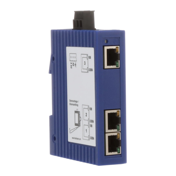
Description and operating instructions
Industrial ETHERNET Rail Switch
P
P
x
x
SPIDER 3TX-TAP
SPIDER 5TX
SPIDER 5TX EEC
P
x
DA/STAT
SPIDER 4TX/1FX
SPIDER 4TX/1FX EEC
SPIDER 4TX/1FX-SM EEC
Hirschmann. Simply a good Connection.
P
x
SPIDER 8TX
SPIDER 8TX EEC
P
x
DA/STAT
SPIDER 4TX/1FX-ST EEC
P
x
DA/STAT
SPIDER 1TX/1FX
SPIDER 1TX/1FX EEC
SPIDER 1TX/1FX-SM
SPIDER 1TX/1FX-SM EEC
SPIDER
SPIDER xTX(/xFX)
The Rail Switches / media converters
– SPIDER 3TX-TAP
– SPIDER 5TX
– SPIDER 5TX EEC
– SPIDER 8TX
– SPIDER 8TX EEC
– SPIDER 1TX/1FX (media converter)
– SPIDER 1TX/1FX EEC (media converter)
– SPIDER 1TX/1FX-SM (media converter)
– SPIDER 1TX/1FX-SM EEC (media converter)
– SPIDER 4TX/1FX
– SPIDER 4TX/1FX EEC
– SPIDER 4TX/1FX-ST EEC
– SPIDER 4TX/1FX-SM EEC
in short SPIDER, are switches especially
designed for use in industrial environments.
It supports ETHERNET 10 MBit/s and Fast
ETHERNET 100 MBit/s.
The devices support switched ETHERNET
networks in accordance with IEEE standard
802.3 or 802.3u using copper and fiber optic
technology. The devices are plugged onto
the standard bar.
The SPIDER 3TX-TAP (SPIDER 5TX, SPIDER
5TX EEC, SPIDER 8TX, SPIDER 8TX EEC)
devices have three (five, eight) 10/100
MBit/s twisted pair ports (RJ45 connectors).
It is possible to connect up to three (five,
eight) data terminal equipments or other
network segments to the TP ports using twi-
sted pair cabling.
The SPIDER 1TX/1FX... devices have one
10/100 MBit/s twisted pair port (RJ45
connectors) and one 100 MBit/s fiber optic
port (100BASE-FX, Duplex SC connector). It
is possible to connect one data terminal
equipments or other network segments to
the TP ports using twisted pair cabling. One
further DTE or optical network component
can be connected to the fiber port.
The SPIDER 4TX/1FX... devices have four
10/100 MBit/s twisted pair ports (RJ45
connectors) and one 100 MBit/s fiber optic
port (100BASE-FX, Duplex SC connector or
ST connector on SPIDER 4TX/1FX-ST EEC).
It is possible to connect up to four data
terminal equipments or other network
segments to the TP ports using twisted pair
cabling. One further DTE or optical network
component can be connected to the fiber
port.
The TP ports support autonegotiation, auto-
polarity and autocrossing.
The fiber optic port of the SPIDER
1TX/1FX... and SPIDER 4TX/1FX... supports
full duplex (FDX).
Advertisement

Related Manuals for Hirschmann SPIDER 5TX EEC


Summarization of Contents
Safety Instructions and Guidelines
General Safety Warnings
Defines warning levels (Danger, Warning, Caution, Note) for safety measures.
Certified Usage
Specifies that devices must only be used as described and within recommended parameters.
Power Supply Safety
Guidelines for connecting devices to the correct power supply and voltage.
Shielding Ground Safety
Precautions regarding short circuits when connecting cables with shielding braiding.
Housing Safety
Instructions regarding authorized personnel, ventilation, and insertion of objects.
Environmental Safety
Guidelines for operating devices within specified ambient temperature and humidity ranges.
Specifications and Standards
Based Specifications and Standards
Lists compliance with various industrial and safety standards like EN, IEC, FCC, CUL.
Notes on CE Identification
Details compliance with European directives for electromagnetic compatibility (EMC).
Functional Description
Frame Switching Functions
Describes store-and-forward mechanism, MAC address learning, and auto-learning.
TP/TX Interface Functions
Covers link control, auto-polarity, and auto-negotiation/autocrossing for twisted pair ports.
F/O Interface Functions
Details link control, low light detection, and Far-End Fault for fiber optic ports.
Further Functions and Features
Includes reset procedures and an overview of equipment status display elements (LEDs).
Interfaces Overview
Details 10/100 MBit/s TP ports and 100 MBit/s FX ports, including pin configurations.
Configuration and Assembly
Connecting DTE and Network Segments
Explains how to connect devices and network segments to the SPIDER ports.
Assembly Procedure
Instructions for unpacking, checking, mounting on DIN rail, and connecting signal lines.
Startup Procedure
Steps to start up the SPIDER by connecting the supply voltage.
Dismantling
Procedure for safely removing the SPIDER from the ISO/DIN rail.
Technical Data
General Data
Provides basic specifications like operating voltage, current consumption, and dimensions.
Environmental Data
Specifies ambient and storage temperatures, humidity, and atmospheric pressure.
Protection and Immunity
Details protection types, pollution degree, laser protection, and EMC immunity levels.
Network Size
Defines the maximum length for twisted pair segments and fiber optic ports.
Product Overview and Support
Fiber Optic Line Length
Specifies example lengths for different fiber optic types (multimode, singlemode).
Interface Summary
Table summarizing interfaces, port types, speeds, and connectors for each SPIDER model.
LED Display Information
Explains the meaning of status LEDs for equipment and individual ports.
Scope of Delivery
Lists the items included in the product package, including order numbers.
Accessories and Contact Information
Provides order numbers for accessories and Hirschmann contact details for support.
Need help?
Do you have a question about the SPIDER 5TX EEC and is the answer not in the manual?
Questions and answers