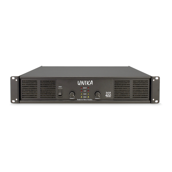
Table of Contents
Advertisement
UNiK A
Professional Power Amplif iers
UNiK A
POWER
PROTECT
CLIP
SIGNAL
0
0
10
10
POWER
0
0
10
10
CHANNEL 1
CHANNEL 2
Professional Stereo Amplifier
UNiK A
POWER
PROTECT
CLIP
SIGNAL
0
0
10
10
POWER
0
0
10
10
CHANNEL 1
CHANNEL 2
Professional Stereo Amplifier
UNiK A
POWER
LIMITER
LIMITER
ON
PROTECT
ON
CLIP
SIGNAL
0
0
10
10
POWER
0
0
10
10
CHANNEL 1
Professional Stereo Amplifier
CHANNEL 2
UNiK A
SIG
-20
-10
-5
CLIP
PROTECT
PROTECT CLIP
-5
-10
-20
SIG
DCA 2000
ON
ON
LIMITER
LIMITER
OVER HEAT
MONO
STEREO
BRIDGE
CHANNEL 1
CHANNEL 2
O
0
10
0
10
PROFESSIONAL POWER AMPLIFIER
Index
02 Introduction
03 Front Panel
05 Rear Panel
07 Set Up
10 Operating Modes
14 Protection
15 Features
16 Specifications
User Instructions
This booklet contains important information concerning the proper and safe operation of your new amplifier..
DCA-Series
DCA-900 / DCA-1100 / DCA-1300 / DCA-2000
Made in Taiwan
Advertisement
Table of Contents

Summarization of Contents
Introduction and Initial Setup
Important Precautions
Key safety guidelines and warnings for unit operation, including electrical shock and environmental hazards.
Unpacking and Initial Inspection
Procedures for checking the amplifier after shipping for any damage or missing parts.
Installation Guidelines
Recommendations for mounting the amplifier in a standard 19" rack for optimal ventilation and security.
Front Panel Controls (DCA-900/DCA-1300)
Mounting Ears and Fan Grills
Describes rack mounting ears and front fan inlet grills for ensuring proper airflow and cooling.
Power Switch and Limiter
Explains the AC power switch and the limiter switch, which reduces distortion during overload.
Indicator Lights
Details signal, clip, and protect indicator LEDs and their meanings during operation.
Gain Control and Power Indicator
Explains the gain adjustment knob for output level and the power status indicator.
Front Panel Controls (DCA-2000)
Mounting Ears and Fan Grills
Describes rack mounting ears and front fan inlet grills for ensuring proper airflow and cooling.
Signal, Clip, Protect, and Overheat Indicators
Explains signal, clip, protect, and overheat LEDs and their meanings during operation.
Limiter Switch and Gain Control
Covers the limiter function and gain adjustment knob for controlling output level.
Mode Selection and Power Switch
Details the mode selection switch for Stereo/Mono/Bridge and the AC power switch.
Rear Panel Connectors and Controls (DCA-1300/DCA-2000)
Fan Outlets and Input Connectors
Describes fan outlets and balanced input connectors (XLR/TRS) for signal input.
Subwoofer Mode and Frequency Adjustment
Covers subwoofer mode switches and frequency adjustment pots for bass frequencies.
Low Cut Filter and Mode Selection
Explains low cut filter switches to remove low frequencies and mode selection switch.
Input Thru and XLR Thru Jacks
Details input thru and XLR thru connections for daisy-chaining signals to other amplifiers.
Rear Panel Outputs and Power
Speaker Output Connectors
Details Speakon and binding post speaker output connectors for speaker connections.
Fuse Holder and Ground Lift Switch
Explains the fuse holder for external fuses and the ground lift switch for hum reduction.
AC Power Connection
Covers AC power cord connection and ensuring correct voltage matching for safety.
System Setup: Inputs and Outputs
Input Connector Types
Explains XLR and 1/4" TRS/TS input options and best practices for balanced/unbalanced connections.
Output Connection Methods
Details binding post, banana plug, and spade connector usage for connecting speakers securely.
Speaker Connection Methods
Bare Wire and Spade Connector Setup
Step-by-step guide for connecting speakers using bare wire or spade connectors to binding posts.
Mono Bridge and Stereo Speakon Connections
Instructions for mono bridge connections and stereo Speakon connections using Neutrik connectors.
Speakon Connector Assembly
Assembling Neutrik Speakon Connectors
Step-by-step guide for assembling Neutrik Speakon NL4FC connectors onto speaker cables.
Operating Modes Overview
Stereo Operation Setup
Guide for setting up the amplifier in stereo mode for dual-channel audio output.
Mono Bridge Operation Setup
Guide for setting up the amplifier in mono bridge mode for increased power output.
Parallel Mono Operation (DCA-2000)
Instructions for parallel mono mode on the DCA-2000 to drive two channels independently.
Advanced Operating Modes
Subwoofer Mode Configuration
How to use subwoofer mode for different configurations like bridge, stereo, or parallel.
Bridge, Stereo, and Parallel Subwoofer Modes
Specifics for setting up bridge, stereo, and parallel subwoofer modes with frequency adjustment.
Bi-Amping Systems
Using amplifier channels independently for bi-amplification of full-range speakers and subwoofers.
Subwoofer Mode Details
Bridge Subwoofer Operation
Setting up bridge mode for high-powered subwoofer use, with load impedance considerations.
Stereo and Parallel Subwoofer Modes
Configuration details for stereo and parallel subwoofer modes, including load limits.
Protection Features and Overload Handling
Limiter Function and Operation
Explanation of the built-in limiter, its activation during signal overload, and distortion reduction.
Load Handling and Thermal Protection
Safe power levels for different loads and how thermal protection engages to prevent overheating.
Short Circuit and Input/Output Protection
Details protection against short circuits, overload, and signal instability.
General Operation and Amplifier Features
Operating Voltage and Gain Adjustment
Proper voltage connection verification and gain control usage for optimal sound.
Amplifier Features: THRU, Ground Lift
Explanation of the THRU function for signal chaining and the ground lift switch for noise reduction.
Low Cut Filter Configuration
How to set up and use the low cut filter to remove unwanted low frequencies from the audio signal.
LED Indicators and Function Indicators
Explains the meaning of various LEDs on the amplifier for signal, clip, protect, and mode status.


Need help?
Do you have a question about the DCA-1100 and is the answer not in the manual?
Questions and answers