Hisense AUD-18HX4SUNL Service Manual
On/off unitory air conditioner
Hide thumbs
Also See for AUD-18HX4SUNL:
- User and installation instructions manual (49 pages) ,
- Technical & service manual (144 pages)
Table of Contents
Advertisement
Advertisement
Table of Contents

Related Manuals for Hisense AUD-18HX4SUNL


Summary of Contents for Hisense AUD-18HX4SUNL
-
Page 1: Service Manual
ON/OFF UNITORY AIR CONDITIONER SERVICE MANUAL V:3.0 UNIT: AUD-18HX4SUNL AUD-48HX6SPHH AUC-18HR4SUAA AUC-48HR6SPHA AUV-18HR4SUA AUV-48HR6SPC AUD-24HX4SZLH AUD-60HX6SPHH AUC-24HR4SZGA AUC-60HR6SPHA AUV-24HR4SZA AUV-60HR6SPC AUD-36HX6SAHH AUC-36HR6SAGA AUV-36HR6SAB Hisense Corporation... -
Page 2: Table Of Contents
Table of contents Page 1.GENERAL 2.SPECIFICATION 2-1 Duct type specifications 2-2 Cassette type specifications 2-3 Ceiling &Floor type specifications 3.OUTLINES AND DIMENSIONS 3-1 INDOOR 3-2 OUTDOOR 4.REFRIGERANT FLOW DIAGRAM 4-1 Refrigerant flow diagram 4-1 ELECTRIC Diagrams 5.ELECTRICAL DATA 5-1 Electric wiring diagrams 5-2 Sensor parameter 6.CONTROL MODE 6-1 Indoor control mode... - Page 3 1.GE ENERAL Features t Type Ai ir Conditi oner eatures Save Inst tallation Spa indoor unit c can be install led inside the e ceiling con nveniently. Optional Static Press 18k: optional 10P Pa /30Pa, 24 4K 36K 50Pa a/80Pa, 48K/ /60K: 80Pa/1 20Pa static Pres...
-
Page 4: 1.General
1.GENERAL space. The unit is also installed with down-air-inlet type. Self Recovery of Power Break When the power supply is recovered after break, all preset are still effective and the air-conditioner can run according to the original setting. Fault Self-diagnose Function When there is something wrong with the air-conditioner,the micro computer could diagnose the faults, which can be read from the display and is convenient for maintenance. - Page 5 1.GE ENERAL Cassette T Type Air Condition eatures Save Inst tallation Spa The indoo or unit can b be installed in nside the ceil ling convenie ently. High Effic ciency and E Environment Friendly New w Refrigeran t-R410A R410A ca an protect th e environme ent and do no...
- Page 6 1.GENERAL Ceiling&Floor Air Conditioner Features Save Installation Space The indoor unit’s thickness is only 230mm,can be installed inside the ceiling conveniently. Flexible Installation Options According to the actual installation space,The indoor unit can be installed in the ceiling or on the floor. One unit, Two installation method. High Efficiency and Environment Friendly New Refrigerant-R410A R410A can protect the environment and do not harm to the ozone layer.
- Page 7 1.GENERAL air-conditioner can run according to the original setting. Fault Self-diagnose Function When there is something wrong with the air-conditioner, the micro computer could diagnose the faults, which can be read from the display and is convenient for maintenance. 5 ...
-
Page 8: Product Lineup
1.GENERAL Product Lineup Type Model Duct Type ● ● ● ● ● Cassette Type ● ● ● ● ● Ceiling&Floor ● ● ● ● ● Type Note:18=18K btu type 6 ... -
Page 9: Model Identification
1.GENERAL 1.3 MODEL IDENTIFICATION 7 ... - Page 10 1.GENERAL 8 ...
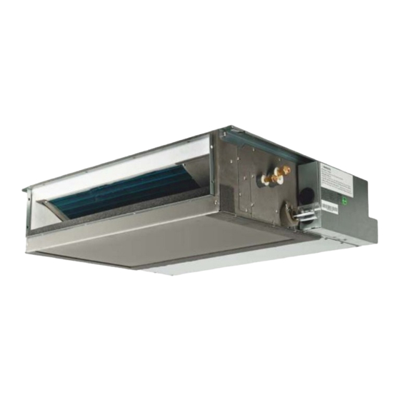
- Page 11 1.GE ENERAL .4 Produ uct Pict ture uct Typ Model AUD-18HX4 4SUNL AUD-24HX4S SZLH ndoor utdoor AUD-48HX6S SPHH Model AUD-36HX6 6SAHH AUD-60HX6S SPHH ndoor utdoor 9 ...
- Page 12 1.GE ENERAL assette T Model UC-18HR4SUA AUC-24HR4 4SZGA Indoor Outdoor AUC-48HR6 6SPHA Model UC-36HR6SAG AUC-60HR6 6SPHA Indoor Outdoor 10 ...
- Page 13 1.GENERAL Ceiling&Floor Type Model AUV-18HR4SUA AUV-24HR4SZA Indoor Outdoor AUV-48HR6SPC Model AUV-36HR6SAB AUV-60HR6SPC Indoor Outdoor 11 ...
-
Page 14: Specification
2.SPECIFICATIONS 2. Specifications 2.1Duct Type Model AUD-18HX4SUNL AUD-24HX4SZLH AUD-36HX6SAHH AUD-48HX6SPHH AUD-60HX6SPHH Power supply Ph-V-Hz 1N,220V~240V/50Hz 3N~,380V-415V/50Hz Cooling Btu/h 17,000 25,300 34,100 47,800 54,600 Capacity 17.5 Heating Btu/h 18,800 26,900 37,500 51,200 59,700 Dehumidification Cooling 1.55 2.45 3.55 4.651 5.694 Rated input Heating 2.19... - Page 15 2.SPECIFICATIONS Model AUD-18HX4SUNL AUD-24HX4SZLH AUD-36HX6SAHH AUD-48HX6SPHH AUD-60HX6SPHH U-V: 2.806;U-W :2.806; U-V: 2433;U-W :2433; U-V: 2433;U-W :2433; Winding resistance(20℃) Ω M:2.1,A:2.81 M:1.37,A:1.7 V-W: 2.651 (at V-W: 2.304(at 25℃) V-W: 2.304(at 25℃) 25℃) Brand GMCC GMCC SANYO SANYO SANYO Model YSK95-45-4-B Y6S419C56...
- Page 16 2.SPECIFICATIONS Model AUD-18HX4SUNL AUD-24HX4SZLH AUD-36HX6SAHH AUD-48HX6SPHH AUD-60HX6SPHH Indoor L×W×H 900×447×190 900×720×270 1300×800×350 1300×800×350 1300×800×350 Dimensions Outdoor L×W×H 800×260×550 900×300×640 950×340×840 950×340×1386 950×340×1386 Indoor L×W×H 1070×580×270 1170×870×340 1550×940×410 1550×940×410 1550×940×410 Packing Outdoor L×W×H 930×360×620 1050×400×700 1100×460×920 1110×460×1530 1110×460×1530 Indoor Net/Gross 20/24...
- Page 17 2.SPECIFICATIONS 2.2 Cassette Type Model AUC-18HR4SUAA AUC-24HR4SZGA AUC-36HR6SAGA AUC-48HR6SPHA AUC-60HR6SPHA Power supply Ph-V-Hz 1N,220V~240V/50Hz 3N~,380V~418V/50Hz 7.45 Cooling Btu/h 17,000 25,400 34,100 47,800 54,600 Capacity 14.8 17.5 Heating Btu/h 18,800 25,600 37,500 50,500 59,700 Dehumidification Cooling 1.55 2.32 4.844 5.694 Rated input Heating 1.55 2.08 4.853...
- Page 18 2.SPECIFICATIONS Model AUC-18HR4SUAA AUC-24HR4SZGA AUC-36HR6SAGA AUC-48HR6SPHA AUC-60HR6SPHA (at20℃) YDK65-6-9024 YDK65-6-9024 Model YDK29-6I-25 YDK70-6H-3 YDK95-6-9043 YDK65-6-9061 YDK65-6-9061 Winding Outdoor resistanc M:83;A1:23.4A2:14 M:231.5;A:168 M:78;A:36.2,51.5,109.2 M:59.1;A:85.8 M:83;A1:23.4A2:14A1:63.5 A1:63.5 (at20℃) type centrifugal fan Indoor Speed Hi/Med/Low r.p.m 720/840/980 270/390/450 480/530/610 450/550/640 450/550/640 Outdoo type r.p.m tube-axial Fan speed...
- Page 19 2.SPECIFICATIONS Model AUC-18HR4SUAA AUC-24HR4SZGA AUC-36HR6SAGA AUC-48HR6SPHA AUC-60HR6SPHA Outdoo Net/Gross 37/42 54/60 71/81 114/124 114/124 Panel Net/Gross 2.4/5 6/7.5 6/7.5 6/7.5 6/7.5 Indoor Hi/Med/Low 35/46 36/43 --/50 46/52 46/52 Noise lever Outdoo Hi/Med/Low --/55 53/58 --/60 --/62 --/62 Gas/Liquid 12.7/6.35 15.88/9.52 15.88/9.52 19.05/9.52 19.05/9.52...
- Page 20 2.SPECIFICATIONS 2.3 Ceiling&Floor type Model AUV-18HR4SUA AUV-24HR4SZA AUV-36HR6SAB AUV-48HR6SPC AUV-60HR6SPC Power supply Ph-V-Hz 1N,220V~240V/50Hz 3N~,380V~418V/50Hz 10.2 Cooling Btu/h 17,000 26,300 34,800 47,800 54,600 Capacity Heating Btu/h 18,800 27,000 40,900 54,600 61,400 Dehumidification Cooling 3.625 4.651 5.694 Rated input Heating 1.595 2.19 3.725 4.523...
- Page 21 2.SPECIFICATIONS (at20℃) 黄:12.39 YDK65-6-9024 YDK65-6-9024 Model YDK29-6I-25 YDK70-6H-3 YDK95-6-9043 YDK65-6-9061 YDK65-6-9061 Outdoor Winding resistance M:231.5;A:168 M:78;A:36.2,51.5,109.2 M:59.1;A:85.8 M:83;A1:23.4A2:14A1:63.5 M:83;A1:23.4A2:14A1:63.5 (at20℃) type centrifugal fan Indoor Speed r.p.m 630/720/800 830/1000/1180 1090/1210/1350 1060/1145/1250 1060/1145/1250 Hi/Med/Low type r.p.m tube-axial Fan speed Outdoor Speed r.p.m 890/920/950 560/780/840 540 / 640 / 800...
- Page 22 2.SPECIFICATIONS Connection method Flare Connection Power wiring 3 core x1.5 3 core x2.5 5 core x1.5 5 core x2.5 5 core x2.5 wiring Signal wiring 5 core x1.5 4core x0.75 4core x0.75 4core x0.75 4core x0.75 Refrigerant charge(R410a) 1.65 Throttle Type Capillary Capillary Capillary...
-
Page 23: Duct Type Specifications
3.Duct Type 3.1 INDOOR... -
Page 25: Cassette Type Specifications
2.Cassette Type (MODEL: AUC-18HR4SUAA)... - Page 26 MODEL: AUC-24HR4SZGA AUC-36HR6SAGA ( 、 、 AUC-48HR6SPHA、AUC-60HR6SPHA)...
- Page 27 3.Ceiling&Floor Type...
-
Page 28: Outdoor
3-2.OUTDOOR (MODEL: AUW-18H4SU) MODEL: AUW-24H4SZ... - Page 29 (MODEL: AUW-36H6SA)...
- Page 31 (MODEL: AUW-48H6SP、AUW-60H6SP)...
-
Page 32: Refrigerant Flow Diagram
4.REFRIGERANT FLOW DIAGRAM 4.Piping Diagrams& ELECTRIC Diagrams 4.1 Piping Diagrams 18K 24K 30 ... - Page 33 4.REFRIGERANT FLOW DIAGRAM 36K 48K、60k 31 ...
-
Page 34: Electric Diagrams
4.REFRIGERANT FLOW DIAGRAM 4.2ELECTRIC Diagrams 18K 24K 36K/48K/60K 33 ... - Page 35 4.REFRIGERANT FLOW DIAGRAM MAX. Refrigerant pipe length and height difference: *Do your best to reduce the pipe length. Long pipe may cause capacity of the indoor unit incline. Total refrigerant pipe length Outdoor unit precharged 0m~5m 5m~60m Xg = 15g / m × (Total pipe length(m) ‐5) AUW-18H4SU 1200g 0g AUW-24H4SZ 1650g 0g AUW-36H6SA 2300g 0g Xg =35g / m × (Total pipe length(m) ‐5) AUW-48H6SP 3100g 0g AUW-60H6SP 3300g 0g 32 ...
-
Page 36: Electric Wiring Diagrams
4.REFRIGERANT FLOW DIAGRAM 4.2ELECTRIC Diagrams 18K 24K 36K/48K/60K 33 ... - Page 37 4.REFRIGERANT FLOW DIAGRAM Recommend Wire Size Power Source Transmitting Model POWER SUPPLY Cable Size Cable Size (mm2) (mm2) 3×1.5 5×1.5 220~240V,50Hz 3×2.5 4×0.75 5×1.5 380~418V,3N~,50Hz 4×0.75 48K/60K 5×2.5 ● Use an ELB (Electric Leakage Breaker). If not used, it will cause an electric shock or a fire.
- Page 38 4.REFRIGERANT FLOW DIAGRAM designation H05RN-F) or ordinary polychloroprene sheathed flexible cord (code designation H05RN-F) . 3) Use a shielded cable for the transmitting circuit and connect it to ground . 4) In the case that power cables are connected in series, add each unit maximum current and select wires below.
- Page 39 4.REFRIGERANT FLOW DIAGRAM Recommend Wire Size Power Source Transmitting Model POWER SUPPLY Cable Size Cable Size (mm2) (mm2) 3×1.5 5×1.5 220~240V,50Hz 3×2.5 4×0.75 5×1.5 380~418V,3N~,50Hz 4×0.75 48K/60K 5×2.5 ● Use an ELB (Electric Leakage Breaker). If not used, it will cause an electric shock or a fire.
- Page 40 4.REFRIGERANT FLOW DIAGRAM designation H05RN-F) or ordinary polychloroprene sheathed flexible cord (code designation H05RN-F) . 3) Use a shielded cable for the transmitting circuit and connect it to ground . 4) In the case that power cables are connected in series, add each unit maximum current and select wires below.
- Page 41 5-1.Electrical wiring diagrams AUD-18HX4SUNL INDOOR: AUD-18HX4SNL...
- Page 42 OUTDOOR: AUW-18H4SU...
- Page 43 AUC-18HR4SUAA INDOOR:AUC-18HR4SAA OUTDOOR: AUW-18H4SU The electrical wiring diagram of outdoor the same as outdoor of MODEL AUD-18HX4SUNL.
- Page 44 AUD-24HX4SZLH INDOOR: AUD-24HX4SLH...
- Page 45 OUTDOOR: AUW-24H4SZ...
- Page 46 AUC-24HR4SZGA INDOOR: AUC-24HR4SGA OUTDOOR: AUW-24H4SZ The electrical wiring diagram of outdoor the same as outdoor of MODEL AUD-24HX4SZLH.
- Page 47 AUD-36HX6SAHH INDOOR: AUD-36HX4SHH...
- Page 48 OUTDOOR: AUW-36H6SA...
- Page 49 AUC-36HR6SAGA INDOOR: AUC-36HR4SGA OUTDOOR: AUW-36H6SA The electrical wiring diagram of outdoor the same as outdoor of MODEL AUD-36HX6SAHH.
- Page 50 AUD-48HX6SPHH、AUD-60HX6SPHH INDOOR: AUD-48HX4SHH、AUD-60HX4SHH...
- Page 51 OUTDOOR: AUW-48H6SP、AUW-60H6SP...
- Page 52 AUC-48HR6SPHA、AUC-60HR6SPHA INDOOR: AUC-48HR4SHA、AUC-60HR4SHA OUTDOOR: AUW-48H6SP、AUW-60H6SP The electrical wiring diagram of outdoor the same as outdoor of MODEL AUD-48HX6SPHH.
-
Page 53: Sensor Parameter
5-2. Sensor parameter 1. THE PARAMETER OF OUTDOOR COMPRESSOR DISCHARGE TEMPERATURE SENSOR: (R =187.25K±6.3%;R =3.77K±2.5K;B0/100=3979K±1%) T [ ℃ ] Rmin [ KΩ ] Rnom [ KΩ ] Rmax [ KΩ ] DR(MIN)% DR(MAX)% 7.47 908.2603 985.5274 1065.1210 -7.84 7.42 855.3955 927.6043 1001.9150 -7.78... - Page 54 T [ ℃ ] Rmin [ KΩ ] Rnom [ KΩ ] Rmax [ KΩ ] DR(MIN)% DR(MAX)% 5.50 107.8202 114.4973 121.1586 -5.83 5.46 102.8560 109.1728 115.4734 -5.79 5.41 98.1470 104.1246 110.0855 -5.74 5.37 93.6787 99.3367 104.9778 -5.70 5.33 89.4378 94.7946 100.1342 -5.65...
- Page 55 T [ ℃ ] Rmin [ KΩ ] Rnom [ KΩ ] Rmax [ KΩ ] DR(MIN)% DR(MAX)% 3.87 17.6458 18.3926 19.1338 -4.06 3.84 16.9986 17.7113 18.4185 -4.02 3.83 16.3784 17.0537 17.7335 -3.96 3.77 15.7839 16.4332 17.0774 -3.95 3.74 15.2139 15.8338 16.4488 -3.92...
- Page 56 T [ ℃ ] Rmin [ KΩ ] Rnom [ KΩ ] Rmax [ KΩ ] DR(MIN)% DR(MAX)% 2.55 4.1453 4.2568 4.3683 -2.62 2.52 4.0218 4.1287 4.2355 -2.59 2.50 3.9024 4.0049 4.1074 -2.56 2.47 3.7872 3.8854 3.9837 -2.53 2.44 3.6758 3.7700 3.8643 -2.50...
- Page 57 2. THE PARAMETER OF THE OTHER SENSOR IN INDOOR AND OUTDOOR UNIT: ( R =15K±2%; B0/100=3450K±2%) T [℃] Rmin [ KΩ ] Rnom [ KΩ ] Rmax [ KΩ ] DR(MIN)% DR(MAX)% 6.12 60.78 64.77 68.99 -6.16 5.83 57.75 61.36 65.16 -5.88 5.57...
- Page 58 T [℃] Rmin [ KΩ ] Rnom [ KΩ ] Rmax [ KΩ ] DR(MIN)% DR(MAX)% 2.11 9.999 10.230 10.450 -2.26 2.23 9.590 9.816 10.040 -2.30 2.33 9.199 9.422 9.647 -2.37 2.40 8.826 9.047 9.269 -2.44 2.48 8.470 8.689 8.910 -2.52 2.57 8.129...
- Page 59 T [℃] Rmin [ KΩ ] Rnom [ KΩ ] Rmax [ KΩ ] DR(MIN)% DR(MAX)% 5.69 2.018 2.140 2.269 -5.70 5.73 1.952 2.072 2.198 -5.79 5.82 1.888 2.005 2.129 -5.84 5.87 1.827 1.941 2.062 -5.87 5.91 1.767 1.880 1.998 -6.01 5.99 1.710...
- Page 60 T [℃] Rmin [ KΩ ] Rnom [ KΩ ] Rmax [ KΩ ] DR(MIN)% DR(MAX)% 8.11 0.5359 0.5835 0.6350 -8.16 8.16 0.5209 0.5675 0.6179 -8.21 8.23 0.5064 0.5519 0.6014 -8.24 8.27 0.4923 0.5369 0.5853 -8.31 8.32 0.4787 0.5224 0.5698 -8.37 8.36 0.4655...
-
Page 61: 6.Control Mode
6-1 Indoor control mode 1.Major general technical parameters 1 Conditionings for operation: Ambient temperatures: (-10 - +43 ℃), relative humidity (45 - 85%). 2 Remote receiver distance: 8 m. 3 Remote receiver angle: Less than 80 degrees. 4 Temperature control accuracy: ±1℃. 5 Time error: Less than 1%. - Page 62 will start in the timer off condition. When the set time is up, the air conditioner will turn off after receiving a signal from the remote controller. If the air conditioner has not received a signal from the remote controller when the set time is up, it will turn off automatically. 3.
-
Page 63: Outdoor Control Mode
The heating mode, remote shutdown, such as indoor heat exchanger temperature is higher, the wind blowing out opportunities continue to run the waste heat. Cool and dehumidification mode , after the compressor close, indoor machine will continue to set the speed of operation for a period of time. 3.9 automatically model This model does not automatically model function, emergency button cannot set the automatic mode of operation, can use the emergency switch shutdown, remote setting the... - Page 64 2. Storage temperature scale: -40℃~85℃ 3. Storage humidity scale: PH30%~PH95% 4. Working temperature:-20℃~85℃ 5. accuracy for temperature control: ±0.5℃ 36k、48 k、60k 1. Voltage scale: 305V~438V,50Hz 2. Storage temperature scale: -40℃~85℃ 3. Storage humidity scale: PH30%~PH95% 4. Working temperature:-20℃~85℃ 5. accuracy for temperature control: ±0.5℃ 2.Control function 2.1Cooling Anti-freeze Protection To prevent indoor air conditioner evaporator temperature is too low, the indoor coil...
- Page 65 Air can heat exchanger temperature sensor for monitoring, when the sensor when the temperature is too high, the compressor will be automatic protection 2.3 Exhaust temperature protection To prevent deterioration due to high exhaust temperature of compressor, the machine will realize the real-time detection of the temperature of exhaust gas. If the temperature is too high compressor automatic protection 2.4 Oil-return Control When the compressor runs for a long time low frequencies, control system will start...
-
Page 66: Error Code
7-1- Error code When the air conditioner failure occurs, air conditioner through three ways to display the fault code. Are: outdoor control board, wire remote controller, display panel. The following is the fault code table Fault Fault of Fault description Remarks code Outdoor environment temperature... - Page 67 Fault Fault of Fault description Remarks code System low pressure causing low pressure switch tripping or pressure Were applied to the low Low voltage switch protection/Low sensors to detect the pressure is pressure switch or a pressure protection shutdown too low to achieve the shutdown pressure sensor type protection pressure The outdoor coil temperature is too...
- Page 68 Fault Fault of Fault description Remarks code Current sensor fault Voltage sensor fault H Pressure sensor fault L Pressure sensor fault IPM fault IPM Communication fault The exhaust temperature is too Too high exhaust temperature high to reach shutdown shutdown temperature Outdoor DC fan fault Outdoor DC fan fault...
-
Page 69: 8.Checking Components
8-1. Check refrigerant system TEST SYSTEM FLOW Conditions: ① Compressor is running. ② The air condition should be installed in good ventilation. Tool: Pressure Gauge Technique: ① see ② feel ③ test ----- Tube defrost. FEEL ----- The difference between tube’s temperature. TEST ----- Test pressure. - Page 70 Test system flow Cooling mode Test system The pressure on the pressure.Does the low high side. pressure normal at service part ? Recharge refrigerant after air purging with If the pressure is The pressure on the the vacuum close to static low side.
-
Page 71: Check Parts Unit
8-2.Check parts unit 1. INDOOR FAN MOTOR MOTOR EXAMINE AND REPAIR Circuit diagram: AUD-18HX4SNL YSK95-45-4-B black black black black gray gray gray gray yellow yellow white white brown orange rad brown orange rad blue blue M1:138Ω A1:42.5Ω A2:22Ω A3:17.6Ω A4:14.6Ω A5:81.4Ω AUC-18HR4SA M:240Ω... - Page 72 AUD-24HX4SLH BROWN-BLUE:70.1 BROWN-ORANGE:75.5 BROWN-RAD:10.3 RAD –WHITE:11.4 WHITE-BLACK:16.1 AUC-24HR4SGA M:209.4Ω A1:36.2Ω A2:51.5Ω A3:109.2Ω AUD-36HX4SHH Y7S423B814...
- Page 73 BLUE- BROWN:52.5 BROWN-RAD:3.78 RAD –YELLOW:3.68 YELLOW–WHITE:0.89 WHITE-BLACK:4.67 ORANGE- BROWN:29.5 AUC-36HR4SGA YDK75-8-2 M:75Ω A:97.5Ω AUD-48HX4SHH\ AUD-60HX4SHH Y7S423C237 BLUE- BROWN:17.89 ORANGE1- BROWN:27.2 BROWN-RAD:3.35 RAD –WHITE:4.77 WHITE-BLACK:2.72 AUC-48HR4SHA/ AUC-60HR4SHA...
- Page 74 YDK80-8-2 M:75Ω A:97.5Ω MOTOR EXAMINE AND REPAIR Circuit diagram: AUV-18HR4SUA YSK110-22-4-A M: 187Ω A1:37.5Ω A2:27.8Ω A3:146Ω AUV-24HR4SZA YSK110-100-4-A...
- Page 75 M:55 Ω A1:23.2 Ω A2:10.9Ω A3:18.3Ω AUV-36HR4SAB Y7S423B212 WHITE-BLACK:41.49 BLACK-BLUE:13.25 BLUE-YELLOW:12.39 RED-BLACK:35.21 AUV-48HR6SPC Y7S423C032 WHITE-BLACK:42.69 BLACK-BLUE:9.19 BLUE-YELLOW:9.09 RED-BLACK:36.41...
- Page 76 Test in resistance. TOOL: Multimeter. Test the resistance of the main winding. The indoor fan motor is fault if the resistance of main winding 0(short circuit)or∞(open circuit). Test in voltage TOOL: Multimeter. Insert screwdriver into to rotate indoor fan motor slowly for 1 revolution or over, and measure voltage “YELLOW”...
- Page 77 2. OUTDOOR FAN MOTOR MOTOR EXAMINE AND REPAIR Circuit diagram AUW-18H4SU YDK29-6I-25 Winding resistance ( at 20℃) M: 231Ω A: 168Ω AUW-24H4SZ YDK70-6H-3: WINDING BROWN " " M The main winding BLACK " " A The auxiliary winding Capacitor ℃ Hot protector 130 WHITE YELLOW...
- Page 78 AUW-48H6SP AUW-60H6SP YDK65-6-9024、YDK65-6-9061 Winding resistance ( at 20℃) M:83.0Ω A1:23.4Ω A2:14.0Ω A3: 63.5Ω Test in resistance. TOOL: Multimeter. Test the resistance of the main winding. The outdoor fan motor is fault if the resistance of main winding 0(short circuit)or∞(open circuit). Notes: 1) Please don’t hold motor by lead wires.
- Page 79 3. COMPRESSOR COMPRESSOR EXAMINE AND REPAIR AUW-18H4SU PA190M2CS-4KTL AUW-24H4SZ(PA290G2CS-4MUL1): AUW-36H6SA (C-SBN303H8D)...
- Page 80 AUW-48H6SP(C-SBN737H8D) AUW-60H6SP(C-SBN453H8D)...
- Page 81 Test in resistance. TOOL: Multimeter. Test the resistance of the winding. The compressor is fault if the resistance of winding 0(short circuit)or∞(open circuit) Familiar error: 1)Compressor motor lock. 2)Discharge pressure value approaches static pressure value . 3)Compressor motor winding abnormality. Notes:...
- Page 82 Fuse PCB Ass'Y Fig.1 2) Check for continuity by a multimeter as shown in Fig.2. Fuse Fig.2 7.CAPACITOR 1) Remove the lead wires from the capacitor terminals, and then place a probe on the capacitor terminals as shown in Fig.3. 2) Observe the deflection of the pointer, setting the resistance measuring range of the multimeter to the maximum value.
-
Page 83: 9.Parts List
9-1. INDOOR ( ) MODEL: AUD-18HX4SUNL... - Page 84 part code description q'ty 1497404 water collecting box assembly 1497776 evaporator ASS'Y 1438672 side panel parts(left) 1438017 mounting plate 1497391 mounting plate assy 1497409 upper board parts 1360744 Fan snail shell 1360739 Centrifugal fan 1360745 Fan snail shell 1497393 air inlet parts 1503294 fan motor 1505112...
- Page 85 (MODEL: AUC-18HR4SAA) 支 撑件 排 水 嘴 固定 夹 (接 水 盘 部 件 )...
- Page 86 PART CODE DESCRIPTION Q'TY NOTE 1249016 fixing clip 1276876 drainage rostra 1506475 air duct plate 1506480 mounting plate 1248404 drain pan 1247663 Centrifugal fan 1496164 fan motor 1248975 motor bracket 1246326 side panel parts 1248202 mounting plate 1246324 side panel parts 1246325 side panel parts 1517496...
- Page 87 1222254 transformer terminal (FOR CONNECT THE INDOOR 1472473 AND OUTDOOR UNIT) 1506968 terminal (electric connect) 1413278 Coil Temperature Sensor 1496065 Room Temperature Sensor 1508138 panel parts 33_1 1225118 step motor 33_2 1248746 axes ring 33_3 1505730 panel 33_4 1505731 Guiding vane 33_5 1508194 air inlet parts...
- Page 88 (MODEL: AUV-18HR4SUA)...
- Page 89 PART CODE PART NO. description Q’ty NOTE 1527351 K31520030 back board parts 1543563 K33120062 mounting plate assy 1543389 K33160080 mounting plate assy 1523844 K33170169 connecting plate 1527689 K37470411 outlet tube ASS'Y 1527685 K37460386 intake tube ASS'Y 1522538 K338A0283 cover 1522338 K33110185 mounting plate 1527615...
- Page 90 terminal (electric 23-2 1506968 K36E10116 cinnect) 1542188 K33540118 elec joint box assy 1522339 K33150447 mounting plate 1527359 K31120289 base parts water collecting box 1529382 K33460024 assembly 1522511 K31470481 panel 1540838 K36430443 display board 1522529 K33210110 ornamental part 1542367 K33280060 displey film 1522522 K33330096 filter...
- Page 91 1543498 K33120060 mounting plate assy 1527679 K37310337 evaporator 1540490 K33AD0141 foam 1527373 K31720065 upper board parts 1540491 K33AD0142 foam remote controller with 1497601 K36210325 Y-J1-05(E) hisense logo wire remote controller Selection 1439489 K36T10016 without logo part (MODEL: AUD-24HX4SLH)...
- Page 92 new part code description q'ty 1492871 flange Electric heater 1413268 evaporator ASS'Y 1493193 mounting plate assy 1492909 motor bracket 1364894 fan motor 1382431 Centrifugal fan 1384111 Fan snail shell assembly 1365389 Fan snail shell 1365383 Fan snail shell 1492886 flange 1492640 upper board parts(left)...
- Page 93 1222254 transformer 1472473 terminal panel 1304089 fixing clip 1485018 elec joint box cover 1492766 side panel parts(right) 1494030 mounting plate assy 1473879 ambient temperature Sensor 1413278 Coil Temperature Sensor 1439489 Wiring remote controller assy (MODEL: AUC-24HR4SGA)...
- Page 94 new part description(chinese) description q'ty code 1515165 base parts 底座部件 1416128 导流板 air duct plate 1503518 fan motor 风扇电机 1509696 side panel 侧板 1509714 风扇蜗壳 Fan snail shell 1514478 water pump 水泵电机 1515344 cover 盖 1515168 排水管部件 drain hose parts 1506379 Centrifugal fan 离心风扇...
- Page 95 27_2 1417920 air inlet parts 进风口部件 27_3 1512376 display film 显示膜片 27_4 1432358 显示板 display PCB remote controller with hisense 1497601 遥控器(海信牌) logo wire remote controller without 1439489 线控器(中性) logo...
- Page 96 AUV-24HR4SZA (MODEL: )...
- Page 97 PART CODE PART NO. description Q’ty 1527351 K31520030 back board parts 1543563 K33120062 mounting plate assy 1543389 K33160080 mounting plate assy 1523844 K33170169 connecting plate 1526151 K37470409 outlet tube ASS'Y 1526167 K37460384 intake tube ASS'Y 1522538 K338A0283 cover 1522338 K33110185 mounting plate 1527615 K31210124...
- Page 98 1527614 K31210123 side panel parts 1543498 K33120060 mounting plate assy 1526357 K37310335 evaporator 1540490 K33AD0141 foam 1527373 K31720065 upper board parts 1540491 K33AD0142 foam remote controller with 1497601 K36210325 hisense logo wire remote controller 1439489 K36T10016 without logo...
- Page 99 AUD-36HX6SAHH (MODEL: )...
- Page 100 new part code description Q’ty 1506878 air outlet parts 1546605 evaporator ASS'Y 1506775 mounting plate 1506798 side panel parts 1506749 mounting plate 1506744 mounting plate 1506684 base parts 1506712 separate plate assy 1506713 motor bracket 1526736 fan motor 1388001 Centrifugal fan 1387893 Fan snail shell assembly 1506884...
- Page 101 1524132 Control Panel Component 32_1 1524127 EEPROM ASS'Y 1222254 transformer 1472473 terminal panel 1304051 polypropylene Capacitor 1485018 elec joint box cover 1506766 card hook 1506706 back board 1401329 water collecting box assembly 1506696 upper board 1413278 Temperature Sensor(White) 1473879 Temperature Sensor(Red) 1439489 Wiring remote controller assy...
- Page 102 AUC-36HR4SGA (MODEL: )...
- Page 103 1428008 Room Temperature Sensor 1512437 front panel parts 27_1 1417915 front panel 27_2 1417920 air inlet parts 27_3 1512376 display film 27_4 1432358 display PCB 1497601 remote controller with hisense logo Y-J1-05(E) 1439489 wire remote controller without logo Selection part...
- Page 104 AUV-36HR6SAB (MODEL: )...
- Page 105 PART CODE PART NO. description Q’ty 1527345 K31520029 back board parts 1543563 K33120062 mounting plate assy 1543389 K33160080 mounting plate assy 1523844 K33170169 connecting plate 1526151 K37470409 outlet tube ASS'Y 1527999 K37460387 intake tube ASS'Y 1527630 K33160076 separate plate assy 1542360 K338A0293 cover...
- Page 106 K33AD0142 foam 1522348 K33150452 mounting plate 1526613 K1B310457 fan motor 1522878 K34310022 holder 1522346 K34310020 holder 1529322 K342B0002 crosshead 1522341 K33150448 mounting plate 1529324 K34220003 axletree remote controller with 1497601 K36210325 hisense logo wire remote controller 1439489 K36T10016 without logo...
- Page 107 AUD-48HX4SHH、AUD-60HX4SHH (MODEL: ) 32-1 30 31 White...
- Page 108 new part code description Q’ty 1506878 air outlet parts 1507292 evaporator ASS'Y 1506775 mounting plate 1506798 side panel parts 1506749 mounting plate 1506744 mounting plate 1506684 base parts 1506712 separate plate assy 1506713 motor bracket 1504618 fan motor 1388001 Centrifugal fan 1387893 Fan snail shell assembly 1506884...
- Page 109 1484990 elec joint box 1506616 Contorl Panel Component 32_1 1506610 EEPROM ASS'Y 1222254 transformer 1472473 terminal panel 1304051 polypropylene Capacitor 1485018 elec joint box cover 1506766 card hook 1506706 back board 1401329 water collecting box assembly 1506696 upper board 1413278 Temperature Sensor(White)...
- Page 110 AUC-48HR4SHA、AUC-60HR4SHA (MODEL: )...
- Page 111 new part code description Q’ty NOTE 1515165 base parts 1416128 air duct plate 1503519 fan motor 1509692 side panel 1509713 Fan snail shell 1514478 Electrical pump 1515344 cover 1515168 drainage hose assy 1506379 Centrifugal fan 1415926 water collecting box assembly 1515164 mounting plate assy 1415955...
- Page 112 AUV-48HR6SPC、AUV-60HR6SPC (MODEL: )...
- Page 113 PART CODE PART NO. description Q’ty NOTE 1527341 K31520028 back board parts mounting plate 1542402 K33120059 assy mounting plate 1543389 K33160080 assy 1522368 K33170166 connecting plate 1529003 K37470412 outlet tube ASS'Y 1528977 K37460388 intake tube ASS'Y 1522538 K338A0283 cover 1522338 K33110185 mounting plate 1527615...
- Page 114 K31210123 side panel parts mounting plate 1542400 K33120058 assy 1529171 K37310344 evaporator 1540492 K33AD0143 foam 1527367 K31720063 upper board parts 1540493 K33AD0144 foam remote controller K36210325 Y-J1-05(E) 1497601 with hisense logo wire remote Selection K36T10016 controller without 1439489 part logo...
-
Page 115: Outdoor
9-2. Outdoor AUW-18H4SU... - Page 116 new part code description q'ty 1317536 propeller fan 1412998 fan motor 1366810 strengthen plate 1366809 motor bracket 1507784 condenser ASS'Y 1463851 side panel 1380772 top cover parts 1377189 electrical box 1306788 running capacitor 1300566 Fan capacitor 1481189 terminal 1222020 4-way valve coil 1408045 4-way valve 1451857...
- Page 117 AUW-24H4SZ...
- Page 118 new part unit description q'ty code price 1489803 fan guard 1492054 front panel 1328932 propeller fan 1301883 fan motor 1378883 motor bracket 1513259 base parts 1498050 separate plate assy 1324726 top cover parts 1326145 Ambient temperature sensor 1466208 condenser ASS'Y 10_1 1464471 outlet tube ASS'Y...
- Page 119 AUW-36H6SA...
- Page 120 KEY NO. PART CODE PART NO. DESCRIPTION QT'Y 1469450 K33350006 side filter 1405350 K38310026 propeller fan 1382782 K33150167 mounting plate 1446243 K1B310344 fan motor 1408125 K331F0057 motor bracket 1400459 K31710028 upper board 1526830 K33670084 separate plate assy 1450004 K37340473 condenser ASS'Y 1469447 K33370020 back guard...
- Page 121 AUW-48H6SP、AUW-60H6SP : Yellow 21-1 26-1 White Black...
- Page 122 AUW-48H6SP new part code description Q’ty 1489805 fan guard 1492061 panel 1470773 guard filter 1405350 propeller fan 1424843 mounting plate 1470988 fan motor 1413664 fan motor 1424737 motor bracket 1424825 separate plate assy 1400459 upper board 1326145 NTC sensor(Yellow) 1435462 condenser 1470773 guard filter...
- Page 123 AUW-60H6SP part code description Q’ty 1489805 fan guard 1492061 panel 1470773 guard filter 1405350 propeller fan 1424843 mounting plate 1470988 fan motor 1413664 fan motor 1424737 motor bracket 1424825 separate plate ass‘y 1400459 upper board 1326145 NTC sensor(Yellow) 1435462 condenser 1470773 guard filter 1506880...
Need help?
Do you have a question about the AUD-18HX4SUNL and is the answer not in the manual?
Questions and answers