Table of Contents
Advertisement
Quick Links
Advertisement
Table of Contents

Related Manuals for AUDAC EPA152


Summary of Contents for AUDAC EPA152
- Page 1 EPA152/252/502 User Manual www.audac.eu...
- Page 2 This manual is put together with much care, and is as complete as could be on the publication date. However, updates on the specifications, functionality or software may have occurred since publication. To obtain the latest version of both manual and software, please visit the Audac website @ www.audac.eu.
-
Page 3: Table Of Contents
Index Introduction Precautions Safety requirements Caution servicing EC Declaration of Conformity Waste of Electrical and Electronic Equipment (WEEE) Caution Chapter 1: Pin connections and connectors Connection standards Chapter 2: Front & rear panel Front panel overview Front panel description Rear panel overview Rear panel description Chapter 3: Connecting the amplifier Input connections... -
Page 5: Introduction
Introduction Dual channel Class-D amplifiers The EPA series are energy efficient Class-D power amplifiers designed for a wide variation of applications, ranging from standard stereo configurations to multi-zone distributed speaker systems. They come available in various models with different output configuration and power ratings. -
Page 6: Precautions
Precautions READ FOLLOWING INSTRUCTIONS FOR YOUR OWN SAFETY ALWAYS KEEP THESE INSTRUCTIONS. NEVER THROW THEM AWAY ALWAYS HANDLE THIS UNIT WITH CARE HEED ALL WARNINGS FOLLOW ALL INSTRUCTIONS NEVER EXPOSE THIS EQUIPMENT TO RAIN, MOISTURE, ANY DRIPPING OR SPLASHING LIQUID. AND NEVER PLACE AN OBJECT FILLED WITH LIQUID ON TOP OF THIS DEVICE. DO NOT PLACE THIS UNIT IN AN ENCLOSED ENVIRONMENT SUCH AS A BOOKSHELF OR CLOSET. -
Page 7: Caution
WASTE ELECTRICAL AND ELECTRONIC EQUIPMENT (WEEE) The WEEE marking indicates that this product should not be disposed with regular houshold waste at the end of its life cycle. This regulation is created to prevent any possible harm to the environment or human health. -
Page 9: Chapter 1: Pin Connections And Connectors
Chapter 1 Pin connections and connectors CONNECTION STANDARDS The in- and output connections for AUDAC audio equipment are performed corresponding to international wiring standards for professional audio equipment. Cinch (RCA): For unbalanced line input connections Tip: Signal Sleeve: Ground White: Left... -
Page 10: Chapter 2: Front & Rear Panel
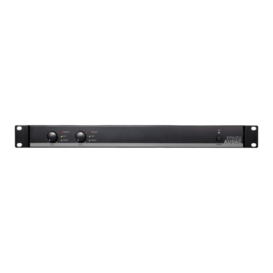
Chapter 2 Front & rear panel Front panel overview PROTECT PROTECT CLIP CLIP EPA502 SIGNAL SIGNAL Front panel description Volume control knobs: These volume control knobs allow level adjustment for each individual channel. Indicator LED’s: These LED’s indicate the operation of the corresponding amplifier channel. A signal indicator, clip indicator and protect indicator are available for each channel. -
Page 11: Rear Panel Overview
IEC C14 power connector and is fitted with a fuse. When replacing the fuse, make sure that the value of the replacement fuse matches the value of the original fuse. (EPA152: T5AL/250V - EPA252: T6.3AL/250V - EPA502: T10AL/250V ) Loudspeaker connections: The loudspeaker output connections for each channel are implemented using both Speakon compatible and terminal block connectors. -
Page 12: Chapter 3: Connecting The Amplifier
Chapter 3 Connecting the Amplifier NOTE Make sure the power is switched OFF when any change is made to the connections of the amplifier. Input connections The signal input connections are implemented using balanced XLR connectors with link output connectors. Each channel is provided with an individual input connection whereto the signal coming from the audio source of pre-amplifier shall be fed, while the link output connectors can be used for linkthrough to other amplifiers. -
Page 13: Connection Modes
- terminals for each individual loudspeaker output connection. Channel 2 Channel 1 EPA502 CH 2 CH 1 CH 2 SPEAKER OUTPUT CH 1 AUDAC Speakon 1 MODE PROFESSIONAL POWER AMPLIFIER CH 1: Stereo Bridge: CH 2: Speakon 2 CH 2:... -
Page 14: Chapter 4: Additional Information
4 Ohm stereo 2 x 150 W 8 Ohm stereo 2 x 80 W 8 Ohm bridge 1 x 300 W EPA252 4 Ohm stereo 2 x 250 W 8 Ohm stereo 2 x 130 W 8 Ohm bridge 1 x 500 W... - Page 15 50/60 Hz (EU) mains network. Internal modification allows this model being used on 110-120V AC - 50/60 Hz (US) mains network. Contact your local service center for more information. Power consumption Standby EPA152 0.8 W EPA252 0.8 W EPA502 0.7 W Idle EPA152 24.1 W EPA252 19.2 W...
-
Page 16: Notes
Notes...
Need help?
Do you have a question about the EPA152 and is the answer not in the manual?
Questions and answers