Table of Contents

Related Manuals for Chromalox 4050


Summarization of Contents
Introduction
Installation
Covers unpacking, installation, panel cut-outs, and panel mounting procedures.
Plug-In Options
Options Modules and Functions
Details the range of plug-in modules for adding input, output, and communication functions.
Auto Detection of Option Modules
Explains how the instrument automatically detects fitted option modules.
Wiring Instructions
Installation Considerations
Provides guidelines for minimizing electrical noise and ensuring good wiring practices.
Power Connections - Mains Powered Instruments
Details connection procedures for instruments powered by 100-240V AC supply.
Universal Input Connections - Thermocouple (T/C)
Explains how to connect thermocouple probes to the instrument's universal input.
Option Slot 1 – Relay Output Module
Describes the wiring for a relay output module fitted in Option Slot 1.
Powering Up
Powering Up Procedure
Step-by-step guide for powering up the instrument for the first time or after changes.
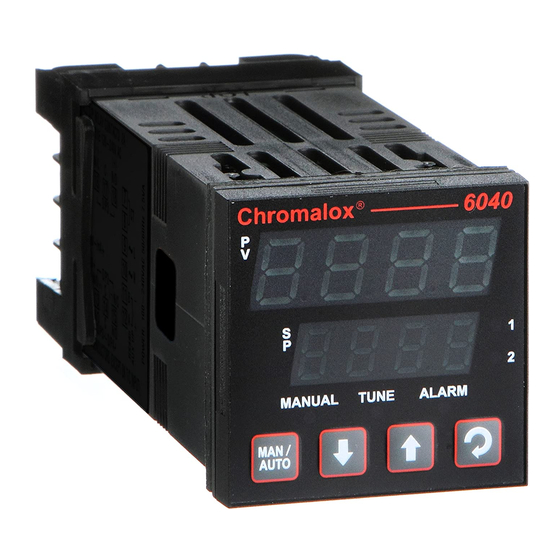
Overview of Front Panel
Illustrates the instrument's front panel and its indicators.
LED Functions
Describes the meaning of the various LED indicators on the front panel.
Instrument Operation Modes
Select Mode
Explains how to gain entry to the instrument's various operating modes.
Unlock Codes
Details the codes required to access Configuration, Setup, and Auto Tuning modes.
Automatic Tune Mode
Describes how to use Pre-tune and Self-tune facilities for controller tuning.
Lock Code View
Entry and Navigating in Lock Code View Mode
Explains how to view and access lock codes for security.
6040, 8040 & 4040 Controller – Model Group
Configuration Mode
Covers initial configuration of the controller's parameters.
Setup Mode
Details how to adjust process setup parameters after initial configuration.
Operator Mode
Describes normal operation, including setpoint adjustments and manual control.
Communications Parameters
Explains Modbus communication parameters for the controllers.
6040, 8040 & 4040 VMD Controller – Model Group
Special Wiring Considerations for Valve Motor Control
Highlights unique wiring requirements for valve motor control.
VMD Configuration Mode
Details the configuration process for Valve Motor Drive controllers.
VMD Setup Mode
Covers setup adjustments specific to Valve Motor Drive functionality.
VMD Operator Mode
Explains how to operate the Valve Motor Drive controllers.
6040 HBA Controller – Model Group
HBA Configuration Mode
Details the configuration parameters for the Heater Break Alarm controller.
6050 & 4050 Limit Controller – Model Group
Limit Controller Configuration Mode
Covers initial configuration settings for Limit Controllers.
Limit Controller Setup Mode
Details setup adjustments for Limit Controllers.
Limit Controller Operator Mode
Explains the operation of Limit Controllers, including setpoint and reset functions.
Serial Communications Parameters
Details serial communication parameters for Limit Controllers.
Manually Tuning Controllers
Single Control Tuning (PID with Primary Output only)
Describes a method for tuning PID controllers with a single output.
Dual Control Tuning (PID with Primary and Secondary Outputs)
Explains tuning for PID controllers with dual outputs (e.g., Heat & Cool).
Valve Control Tuning (PI with VMD or Linear Outputs)
Details tuning techniques for PI control of modulating valves.
Modbus Serial Communications
Supported Modbus Functions
Lists the Modbus function codes supported by the instruments.
ASCII Communications – NOT RECOMMENDED
Session Layer
Describes the session layer for ASCII communication protocols.
Calibration Mode
Recalibration Procedure
Step-by-step guide for recalibrating the instrument's universal input.
Appendix 1 - Glossary
PID Control
Defines Proportional Integral and Derivative control.
Process Variable (PV)
Explains the variable measured by the primary input of the instrument.
Self-Tune
Describes the automatic process of optimizing controller tuning.
Appendix 2 - Specification
Universal Input
Details the general specifications for the universal input.
Control Specifications
Lists specifications for tuning, control modes, and setpoint parameters.
Physical Specifications
Provides dimensions, mounting details, and terminal information.
Appendix 3 - Order Tables
40 Series 1/16, 1/8, 1/4 DIN Temperature & Process Controller
Order table for the 40 Series Temperature & Process Controllers.
Need help?
Do you have a question about the 4050 and is the answer not in the manual?
Questions and answers