
Related Manuals for Chromalox CFW


Summary of Contents for Chromalox CFW
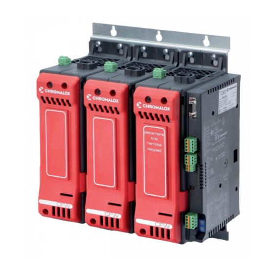
- Page 1 Hardware Instruction Manual Modular SCR Power Controller with Independent PID control PK558 0037-75584 March 2019...
-
Page 3: Table Of Contents
Table of Contents Important Safeguards ......................1 1. Initial Instructions ......................2 1.1 General Description ..........................2 1.2 Features ..............................2 1.3 Product Inspection ..........................3 2. Dimensions & Weights ...................... 4 2.1 Template Dimensions ..........................6 2.2 Installation ............................... 7 3. - Page 4 9. Firing (Trigger) Mode Overview ..................61 9.1 Trigger Modes ............................61 9.2 Digital Input or PWM (40 to 300A) ......................65 9.3 Digital Input or PWM (400 to 600A) ....................... 66 10. Installation of Modbus Serial Network ................67 11.
-
Page 5: Important Safeguards
Important Safeguards This controller utilizes a heat sink which is de- HIGH VOLTAGE (up to 690 VAC) is used in the signed to cool the unit during operation. Un- operation of this equipment; DEATH ON CON- der no circumstance should air flow around the TACT may result if personnel fail to observe controller be compromised in any way. -
Page 6: Initial Instructions
RMS current level at full power under control. In particular, this new line of Chromalox solid state re- lays is the ideal solution for sectors demanding high Thanks to sophisticated Hardware and Software solu- performance and continuity of service, such as: tions, you can precisely control different types of loads. -
Page 7: Product Inspection
Read the following preliminary instructions before in- the section: “Technical-Commercial Information.” stalling and using the CFW modular power controller. See paragraph “ Dimensions and mounting” before in- This will make start-up faster and avoid some prob-... -
Page 8: Dimensions & Weights
2. Dimensions and Weights CFW 40A to 300A Dimensions, In. (mm) 4.26” (108.4) 9.37” (238) 6.70” (170.39) 3.3”(84) 7.31” (185.81) CFW1 1.65”(42) Weights Lbs (kg) Weight 11.9” Model Amps Lbs (kg.) (302) CFW1 40/60/100 4.85 (2.2kg) 11.31” CFW2 40/60/100 9.25 (4.2kg) (287.4) - Page 9 CFW 400A to 600A Dimensions, In. (mm) 11.81” (300) 5.70” (145) 2.56” (65) 11.25” (286) 3.74” (95) CFW1 13.78” (350) 13.34” (339) 2.56” (65) CFW2 9.45” (240) 7.48” (190) 2.56” 2.56” (65) (65) Weights Lbs (kg) Weight Model Amps Lbs (kg.) CFW1 17.63 (8 Kg)
-
Page 10: Template Dimensions
2.1 Template Dimensions Panel Mounting and Cutout Dimensions - 40 to 300A Models CFW MASTER CFW2 CFW3 Fastening may be done with (5MA). All dimensions are expressed in mm. Panel Mounting and Cutout Dimensions - 400 to 600 A Models... -
Page 11: Installation
2.2 Installation 40 to 300A Models ATTENTION: RESPECT THE MINIMUM DIS- TANCES SHOWN TO PROVIDE ADEQUATE AIR CIRCULATION. Place here Place here the remore the remore keypad keypad 400 to 600A Models... -
Page 12: Installation And Connection
In compliance with Directive 2014/30/EU and following • use braided and shielded cables, with sheathing modifications. grounded at a single point. Series CFW are mainly intended for industrial use, in- stalled on panels or control panels of production pro- 3.3.3 Installation notes cess machines or systems. - Page 13 • Vertical distance between a device and the next one model). at last 300mm. • presence of dispersion current in CFW in noncon- • Horizontal distance between a device and the next ducting state (current of a few mA due to RC Snub- one at last 10mm.
- Page 14 Installation Diagram – 400 to 600A PORT 2 PORT 1 Fieldbus MODBUS RS485 MODBus RS485 Ethernet Modbus TCP Ethernet-IP Ethercat CanOpen 500V Pro bus INPUTS OUTPUTS ANALOG COMMAND INPUT 5,6,7,8, Analog / Digital Main Processor TA INPUT (I_load) TA1, TA2, TA3 EEprom DIGITAL INPUTI DI1, DI2, DI3, DI4...
-
Page 15: Emission, Immunity And Safety Standards
EMC filters are required in Phase Angle firing mode. The filter model and current level depend on the configura- tion and load used. The power filter MUST be connected as close as possible to the CFW. You can use a filter connected between the power line and CTF or an LC group connected between the CFW output and the load. - Page 16 EMC filters are required in Phase Angle firing mode. The filter model and current level depend on the configura- tion and load used. The power filter MUST be connected as close as possible to the CFW. You can use a filter connected between the power line and CTF or an LC group connected between the CFW output and the load.
-
Page 17: Controller Overview
5. Controller Overview 40 to 300A Models Line / load voltage connector Control input connector “Line” terminals Address Rotary Switch Configuration keypad connector input connector PID Output connector RJ10 connector serial RS485 (PORT 1) Supply connector Dip Switch serial line (PORT 1) Digital input connector Connector board Fieldbus (PORT 2) 4 input TCAUX connector... - Page 18 Rotary Switch (address) 3-way external TA input connector 3 analog input connector Port2 Fieldbus connectors and led Connector for CFW-OP keypad Operating status led 24 V fan power supply output connector Port1 RS 485 Modbus RTU Load terminal (pre-split protection grid)
-
Page 19: Cleaning/Checking Or Replacing The Fan - 40 To 300A Models
5.1 Cleaning/Checking or Replacing the Fan – 40 to 300A Models IN CASE OF OVERHEAT ALARM: Periodic CleaningEvery 6-12 months (de- pending on the dust level of the installation) If periodic cleaning does not eliminate the problem, do blow a compressed air jet downward as follows: through the upper rectangular cooling grilles (on the 1. -
Page 20: Cleaning/Checking Or Replacing The Fan - 400 To 600A Models
0.8 that the CFW has been turned off and cut off from the electrical power supply to ensure the operator’s safety: 7. Insert the fan’s 24V power supply connector. -
Page 21: Replacing The Internal Fuse (Optional) - 40 To 300 A Models
4. Loosen the two fastening nuts of fuse by means of tube-shaped spanner N.13 (CFW 40...150) 5. It is not necessary to remove the nuts as the fuse N.17 (CFW 200...300 A) is slipped off its seat by turning it (4) and extracting it (5) as indicated by the arrows 6. -
Page 22: Replacing The Internal Fuse (Optional) - 400 To 600 A Models
1. Unscrew the screw (1) holding the cover in place 2. Remove the cover, in the direction shown by the ar- 7. Tighten the two nuts with a No. 19 spanner (CFW row (2). 500/600A) or a No. 17 spanner (CFW 400A), to a torque of 12 Nm. -
Page 23: Card Insertion For Fieldbus Interface - 40 To 300 A Models
5.5 Card Insertion for Fieldbus Interface – 40 to 300 A Models 1. Undo the screws 16. 6. Replace cover 17 in its seat. 2. Turn slightly the points 18 using a screwdriver. 7. Fasten the screws 16. 3. Remove the cover 17. 4. -
Page 24: Card Insertion For Fieldbus Interface - 400 To 600 A Models
5.6 Card Insertion for Fieldbus Interface – 400 to 600 A Models 1. Slacken the screws (1) on the front piece and re- 5. Use the new front piece (2) supplied with the Field- move the front piece (2). bus card (or open the pre-fractured parts present on the product’s original front piece) and fix it in place 2. -
Page 25: Connection Of Expansion Modules (For 2-Phase Or 3-Phase Configuration)
10. Check the front covers are properly closed with the module to the panel as described at paragraph 2.4. screws. CFW-E CFW-E CFW-M... -
Page 26: Connections And Indicators
OUT 6 OUT 7 Screw front cover Optional outputs OUT 8 (allows access to fuse) OUT 9 (Relay N.O.) Magnetic area OUT 10 (Relay N.O.) keypad fixing CFW-OP (only CFW-M model) Outputs RUN....(Green) ERROR..(Red) +24 vdc DI1....(Yellow) Supply GND - SUPPLY DI2....(Yellow) - Page 27 4/L2 (DIN or cable) external CT (optional) (Ref. V_Line) TA1+ TA1 - Connector TA2+ for Keypad TA2 - V-Load CFW-OP TA3+ Connector (optional) TA3 - 1/L1 Power line input 5/T1 (DIN or cable) 6/T2 (Ref. V_Load) Auxiliary outputs Front View...
-
Page 28: Connections - 40 To 300A Models
6.1 Connections – 40 to 300A Models If auxiliary outputs (O5...O8), are present, connector J1a becomes J1. 0.2 - 2.5mm 24-14 AWG 0.25 - 2.5mm 23-14 AWG Outputs 5...8 logic/continuous type Logic outputs 18...36Vdc, max 20mA Continuous outputs: voltage (default) 0/2...10V, max 25mA current 0/4...20mA, max 500Ω... - Page 29 When using the continuous “C” output option, voltage or current is set using jumper links on the board. Internal OUT - C board (optional) Voltage settings Current settings OUT – C Board OUT – C Board...
- Page 30 Com 5÷8 Outputs 5...8 Triac Type Triac outputs Vac = 24...230Vac, max 1A Connection Scheme for Triac Outputs Com 5÷8 Name Description Com 5÷8 Com 5-8 Outputs common Output 5 Output 6 Output 7 Output 8 Outputs 5...8 Relay Type Outputs Out 5...8 relay Ir = 3A max, NO Com 5÷8 V = 250V/30Vdc cos = 1;...
-
Page 31: Connector J2 Power Supply
6.2 Connector J2 Power Supply 0.2 - 2.5mm 24-14 AWG 0.25 - 2.5mm 23-14 AWG Name Description +24 VDC 24V Supply 24V Supply Earth Ground 6.3 Connector J2 Digital Input 0.14 - 0.5mm 28-20 AWG 0.25 - 0.5mm 23-20 AWG Connection Scheme for Digital Input Name Description... -
Page 32: Connector J3 Auxiliary Inputs 5
6.4 Connector J3 Auxiliary Inputs 5...8 0.14 - 0.5mm 28-20 AWG 0.25 - 0.5mm 23-20 AWG Auxiliary inputs I5 - I8 (60mV/TC) Name Description Auxiliary Input 2 Auxiliary Input 2 Auxiliary Input 3 Auxiliary Input 3 Auxiliary Input 4 Auxiliary Input 4 Auxiliary Input 5 Auxiliary Input 5... -
Page 33: Connector J5 Analog Input Control (40 To 300A)
6.5 Connector J5 Analog Input Control (40 to 300A) 0.2 - 2.5mm 24-14 AWG 0.25 - 2.5mm 23-14 AWG Connection Scheme Name Description +5V_Out Supply Outut 5V Potentiometer Control Voltage Input SHUNT Shunt for INput mA GND Control Signal... -
Page 34: Connector J6 Pid Input (40 To 300A)
6.6 Connection J6 PID Input (40 to 300A) 0.2 - 2.5mm 24-14 AWG 0.25 - 2.5mm 23-14 AWG Connection Scheme for 60mV TC/Linear Input Connection Scheme for Pt100 Input Name Description EARTH EMC Earth (for shielded cable) Negative Input Positive Input TC and RTD 3rd Wire RTD, Positive IN mA Connection Scheme for 1V/20mA LinearInput Linear Input... -
Page 35: Connector J1 Outputs 5
6.7 Connection J1 Outputs 5...10 (400 to 600A) Connector J1 will be assembled in the presence of auxiliary outputs (O5...O8). 0.25 - 2.5mm 23-14 AWG 0.25 - 2.5mm 23-14 AWG OUTPUTS 5...8 Logical (option D) / Analog (option W) Logic outputs: 18...36Vdc, max 20mA Continuous outputs: voltage (default) 0/2...10V, max Description 25mA current 0/4...20mA, max 500Ω... -
Page 36: Connector J2 Outputs 9, 10 (400 To 600A)
6.8 Connector J2 Outputs 9, 10 (400 to 600A) 0.25 - 2.5mm 23-14 AWG 0.25 - 2.5mm 23-14 AWG RELAY OUTPUTS 9, 10 Outputs Out 9, 10 relay 5A max, Relay with exchange contact (C, NC, NO) V = 250V/30Vdc cosφ = 1; I = 5A max Connection Scheme for Relay Outputs Description Name... -
Page 37: Connector J3 Power Supply And Digital Inputs (400 To 600A)
6.9 Connector J3 Power Supply and Digital Inputs (400 to 600A) 0.25 - 2.5mm 23-14 AWG 0.25 - 2.5mm 23-14 AWG Description Name +24Vdc 24 Vdc supply 24 Vdc supply Earth Earth EMC Digital input 1 (5 … 32Vdc) + INDIG1 configurable NPN / PNP Digital input 2 (5 …... -
Page 38: Connector J4 Analog Control Inputs (400 To 600A)
6.10 Connector J4 Analog Control Inputs (400 to 600A) 0.25 - 2.5mm 23-14 AWG 0.25 - 2.5mm 23-14 AWG Connection Scheme Description Name Output 5V potentiometer(s) power +5V_POT supply (max 30 mA) +INA1 Analogue command input INA1 GND command signal EARTH Earth EMC +INA2... -
Page 39: Connector J5 External Ta Inputs (Optional) (400 To 600A)
6.11 Connector J5 External TA Inputs (Optional) (400 to 600A) 0.25 - 2.5mm 23-14 AWG 0.25 - 2.5mm 23-14 AWG Connection Scheme Description Name TA1+ External TA1 input (max 5 A rms) TA1- External TA1 input (max 5 A rms) TA2+ External TA2 input (max 5 A rms) TA2-... -
Page 40: Electrical Connections
7. Electrical Connections Recommended Wire Gauges CFW Current Tightening / Level Terminal Wire Gauge Terminal Type Tool Torque Wire stripped for 25 mm or 10 mm with crimped pre-insulated 5 Nm / Flat-head screwdriver 1/L1, 2/T1 7 AWG terminal tube tip 1 x 5.5 mm... - Page 41 Recommended Wire Gauges ?.? Power Connections (400 to 600A) CFW Current Type Cable/Selection Terminal Type Tightening / Level Terminal Type Rail/Selection Cable /Rail Tool Torque Single cable N. 1 Bolt M12x25mm UNI 5739 Wire crimped at terminal 400A 1/L1, 2/T1 300 mm hex head wrench n.
- Page 42 Description Defines address of module 00...99 (in case of CFW compatible mode (dip switch 7= ON), this address is attributed to the CFW Master module; the expansions, if present, will have address +1 (CFW Expanasion Slot 1) and address +2 (CFW Expansion Slot 2)) Hexadecimal combinations are reserved.
-
Page 43: Description Of Dip-Switches (40 To 300A)
Connection type: (see table) OFF = resistive load ON = inductive load (transformer primary control) ON = reset factory configuration ON = Chromalox simulation function Recommended Wire Gauges Request Modules Dip 1 Dip 2 Dip 3 Dip 4 Dip 5... -
Page 44: Serial Communication Ports (40 To 300A)
7.2 Serial Communication Ports (40 to 300A) Port1 (local bus): Modbus Serial Interface – Connectors S1, S2. Connector S1/S2 RJ10 4-4 pin Nr. Pin Name Description Note GND1 (**) (*) Insert the RS485 line termination in the last device on Tx/Rx+ Data reception/transmission (A+) the Modbus line, see dip-switches. - Page 45 Port2 (fieldbus): Connectors S4, S5 MODBUS RTU/MODBUS RTU Connector S5 Connector S4 Line termination (*) Connector S4/S5 RJ10 4-4 pin Nr. Pin Name Description Note GND1 (**) (*) Insert the RS485 line termination in the last device on Tx/Rx+ Data reception/transmission (A+) the Modbus line, see dip-switches.
- Page 46 Port2 (fieldbus): Connectors S4, S5 MODBUS RTU/Profibus DP Connector S4 RJ10 4-4 pin Nr. Pin Name Description Note GND1 (**) Rx/Tx+ Data reception/transmission (A+) (**) Connect the GND signal between Modbus devices with a line distance > 100 m. Rx/Tx- Data reception/transmission (B-) +V (reserved) Cable type: flat telephone cable for pin 4-4 conductor 28 AWG...
- Page 47 Port2 (fieldbus): Connectors S4, S5 MODBUS RTU/CANopen Connector S4 RJ10 4-4 pin Nr. Pin Name Description Note GND1 (**) Rx/Tx+ Data reception/transmission (A+) (**) Connect the GND signal between Modbus devices with a line distance > 100 m. Rx/Tx- Data reception/transmission (B-) +V (reserved) Cable type: flat telephone cable for pin 4-4 conductor 28 AWG Connector S5...
- Page 48 Port2 (fieldbus): Connectors S4, S5 MODBUS RTU/Ethernet Modbus TCP S5 female connector S4 female connector Connector S4 RJ10 4-4 pin Nr. Pin Name Description Note GND1 (**) Rx/Tx+ Data reception/transmission (A+) (**) Connect the GND signal between Modbus devices with a line distance >...
- Page 49 Port2 (fieldbus): connectors S4, S5 Modbus RTU / Ethernet IP or Modbus RTU / EtherCAT Connector S4 RJ10 4-4 pin Nr. Pin Name Description Note GND1 (**) Rx/Tx+ Data reception/transmission (A+) (**) Connect the GND signal between Modbus devices with a line distance >...
-
Page 50: Connection Example: Power Section
Dip 5 if resistive load cosϕ=1 FAST FUSE: needed only for controller with option Fuse = 0 GG Fuse: See Fuse section CFW Connection Example for 1 Single-Phase Transformer Load (*) Only required with Vload measurement input option. V = phase voltage (line L1- line L2/N) - Page 51 FAST FUSE: needed only for controller with option Fuse = 0 GG Fuse: See Fuse section CFW 3-Phase, 2-Leg connection for a 3-Phase Star Load without Neutral with Transformer (*) Only required with Vload measurement input option.
- Page 52 ϕ if resistive load FAST FUSE: needed only for controller with option Fuse = 0 GG Fuse: See Fuse section CFW 3-Phase, 2-Leg connection for a 3-Phase Closed Delta Load with Transformer (*) Only required with Vload measurement input option.
- Page 53 Dip 3 Dip 4 Dip 5 FAST FUSE: needed only for controller with option Fuse = 0 GG Fuse: See Fuse section CFW Connection Example for 1 3-Phase Closed Delta Load with Transformer (*) Only required with Vload measurement input option.
- Page 54 Dip 4 Dip 5 FAST FUSE: needed only for controller with option Fuse = 0 GG Fuse: See Fuse section CFW Connection Example for 1 3-Phase Star Load without Neutral with Transformer (*) Only required with Vload measurement input option.
- Page 55 CFW Connection Example for 1 3-Phase Star Load with Neutral Only required with Vload measurement input option. - FIRING MODE: ZC, BF, HSC, PA - HB DIAGNOSTIC AVAILABLE: V= line voltage CFW Master - Dip-Switch Configuration Partial and total load failure of each single leg...
- Page 56 CFW Connection Example for 3 Independent Loads in Open Delta, 3-Phase Line without Neutral V= line voltage P = power of each single-phase load (*) Only required with Vload measurement input option. Id = load current if resistive load cosϕ=1...
- Page 57 Dip 4 Dip 5 Fast Fuse Needed only for controller with option Fuse = 0 GG Fast Fuse See Fuse section CFW Connection Example for 1 Single-Phase Transformer Load IMPORTANT: Take care to connect terminals 1/L1 and 3/L1 to the same...
- Page 58 CFW 2-PH for 2 Independent Single Phase Loads It is possible to connect two single-phase loads also to different line voltages, between line to line or line to neutral. It is possible to manage different power values for each one of the two loads.
- Page 59 Fast Fuse Needed only for controller with option Fuse = 0 GG Fast Fuse See Fuse section CFW Connection Example 3-Phase, 2-Leg Connection for a 3-Phase Star Load without Neutral with Transformer Control option = 0 Control option = 3 (Vload input)
- Page 60 Fast Fuse Needed only for controller with option Fuse = 0 GG Fast Fuse See Fuse section CFW Connection Example 3-Phase, 2-Leg Connection for a 3-Phase Closed Delta Load with Transformer Control option = 0 Control option = 3 (Vload input)
- Page 61 Dip 4 Dip 5 GG Fast Fuse See Fuse section CFW Connection Example for 1 3-Phase Closed Delta Load with Transformer Control option = 0 Control option = 3 ( Vload input ) Control option = 4 (Vload input and external TA input)
- Page 62 Dip 2 Dip 3 Dip 4 Dip 5 CFW Connection Example for 1 3-Phase Star Load without Neutral with Transformer Control option = 0 Control option = 3 (Vload input) Control option = 4 (Vload input and external TA input)
- Page 63 CFW Connection Example for 1 3-Phase Star Load with Neutral (*)IMPORTANT: Take care to connect terminals 1/L1 and 3/L1 to the same phase (**)Only required with Vload measurement input option. V line voltage Vd load voltage P total power Id current in three-phase load if resistive load cosφ =1...
- Page 64 CFW Connection Example for Independent Loads in Open Delta, 3-Phase Line without Neutral (*)IMPORTANT: Take care to connect terminals 1/L1 and 3/L1 to the same phase (**)Only required with Vload measurement input option. V line voltage P power of each single-phase load Id load current if resistive load cosφ=1...
-
Page 65: Inductive & Transformer Coupled Load Guidelines
3. In ZC and BF trigger mode, use the Delay-triggering function to limit peak magnetization current. 1. when the CFW is working it is not allowed to open 4. In PA trigger mode, use the Softstart function. neither the connection between CFW and the trans- 5. - Page 66 This mode corresponds to Burst Firing that manages ON and OFF half-cycles. It is useful for reducing the flickering of filaments with short/medium-wave IR lamp loads. With these loads, to limit operating current with low power, it is useful to set a minimum power limit (for example Lo.P = 10%, ref “CFW-IR operation guide”).
- Page 67 ADDITIONAL FUNCTIONS Softstart This type of start can be enabled either in phase control or pulse train mode and in zero-crossing mode (ZC, BF, HSC). In phase control, the increment of conduction angle q stops at the corresponding value of the power to be trans- ferred to the load.
- Page 68 DT - Delay Triggering “Delay triggering” (for ZC, BF control modes only) Settable from 0° to 90°. Useful for inductive loads (transformer primaries) to prevent current peak that in certain cases could trip the high- speed fuses that protect the SCRs. Transient with Transient without Over-Current...
-
Page 69: Digital Input Or Pwm (40 To 300A)
Temperature control with Chromalox 600 with D type logic output (out2) (cycle time: 0.1sec), CFW without The sum of TON+TOFF is constant, and is called Cy- PID option, logic output can drive max 3 CFW in series cleTime. (preferable), connection allowed only if CFWs do not... -
Page 70: Digital Input Or Pwm (400 To 600A)
The signal can be generated by a controller or external to the cycle time from 0.03Hz to 100Hz and obtains plc via digital outputs (logic output for Chromalox in- the power % to be supplied to the load from the TON/ strumentation). -
Page 71: Installation Of Modbus Serial Network
16. (ID) set on rotary switches (tens + units). Procedure A maximum of 99 CFW, modules can be installed in a 1. Connect the serial cables for all modules on the net- serial network, with node address selectable from “01”... -
Page 72: Technical Characteristics
Voltage Linear: 0,…,10Vdc, Ri>100Kohm Current Linear: 0/4…20mA, Ri =125ohm Potentiometric 1, ..., 10Kohm, max 10mA from 5Vdc power CFW IN1 Analog Process Inputs (Option) Function Acquisition of process variable Max. error 0,2% f.s. ± 1 scale point at @ 25°C Thermal drift <... - Page 73 OUT9, OUT10 Alarm Function Function Configurable (default alarms) Relay Contact NO 5A, 250V/30Vdc cosf =1 COMMUNICATIONS PORTS (40 to 300A Models) PORT CFW-OP Serial comunication for KB-ADL terminal to display parameter Function programming PORT 1 Always Present Function Function Local serial communication...
- Page 74 For models with integrated fuse, also consider dissipated power at Thermic Dissipation rated current shown on the fuse table CFW models with electronic fuse (with internal IGBT) dissipate thermic power based on load current: Pdissipation = I_load_Arms * 2.8V (W)
- Page 75 FUNCTION (40 to 300A Models) Detection of short circuit or opening of inputs, absence of input feed, LBA Safety alarm, HB alarm Selection of °C/°F Configurable Linear scale range -1999…9999 1 control loops: Control Actions Double action (heat/cool) PID, on-off Self-tuning at start, continuous Autotuning, one-shot Autotuning PID parameters: pb-dt-it 0,0...999,9 % –...
- Page 76 GENERAL DATA (40 to 300A Models) 24Vdc ±10%, Clas II, max 8VA Power Supply Max 10VA with CFW-OP terminal - isolation 1000V Fan power supply 24Vdc ±10%, 500mA @ 25Vdc Eight leds: RN (Green) run state of CPU ER (Red) error signal...
- Page 77 Linear: 0,…,10Vdc, Ri>90Kohm Current Linear: 0/4…20mA, Ri =250ohm Potentiometric 1, ..., 10Kohm, max 30mA from 5Vdc power CFW Line Voltage Measurement, Current /Voltage (optional) on Load Line voltage read 50-60Hz; voltage in range: 90...530Vac for model with work voltage range 480Vac RMS line current measurement function 90...660Vac for model with work voltage range 600Vac...
- Page 78 OUT9, OUT10 Alarm Function Function Configurable (default alarms) Relay Contact in exchange (C, NO, NC) 5A, 250V/30Vdc cosf =1 COMMUNICATIONS PORTS (400 to 600A Models) PORT CFW-OP Serial comunication for KB-ADL terminal to display parameter Function programming PORT 1 Always Present Function...
- Page 79 For models with integrated fuse, also consider dissipated power at Thermic Dissipation rated current shown on the fuse table CFW models with electronic fuse (with internal IGBT) dissipate thermic power based on load current: Pdissipation = I_load_Arms * 2.8V (W)
- Page 80 1 phase load star with neutral 1 phase load star without neutral GENERAL DATA (400 to 600A Models) CFW 1PH-400/500/600A: 24Vdc +/- 10% max 38W Power Supply CFW 2PH-400/500/600A: 24Vdc +/- 10% max 66W CFW 3PH-400/500/600A: 24Vdc +/- 10% max 94W Fan power supply 24Vdc ±10%, 500mA @ 25Vdc...
- Page 81 2PH or 3PH Dimensions 310x170x225 mm 410x355x260 mm 400 to 600A Model with Models Internal Fuse CFW1 CFW2 CFW3 CFW 400 15.5kg 22.5kg Weight CFW 500/600A 11kg 21kg 31kg Packaging CFW1 CFW2 & CFW3 Dimensions 420 x 480 x 250 mm 420 x 520 x 510 mm 11.1 Derating Curves...
-
Page 82: Ordering Information
12. Ordering Information Ordering Information To Order — Complete the Model Number using the Matrix provided. Model CFW Advanced Modular SCR Power Controller CFW1 Single Phase CFW2 Three Phase, 2-leg CFW3 Three Phase, 3-leg Code Current @ 104˚F (40˚C) Ambient, continuous service... -
Page 83: Accessories
• Easy and rapid configuration • Saving and management of parameter recipes • On-line trend and saving of historical data Component Kit: - Connection cable PC USB <----> CFW RS485 port - Serial line converter - C-PWR Digital Download http://www.chromalox.com/en/resources-and-support/software Fuses – Extra Rapid... - Page 84 Limited Warranty: Please refer to the Chromalox limited warranty applicable to this product at http://www.chromalox.com/customer-service/policies/termsofsale.aspx. Chromalox, Inc. 1347 Heil Quaker Boulevard Lavergne, TN 37086 (615) 793-3900 www.chromalox.com © 2016 Chromalox, Inc.
Need help?
Do you have a question about the CFW and is the answer not in the manual?
Questions and answers