
Subscribe to Our Youtube Channel
Related Manuals for Chromalox 3101


Summary of Contents for Chromalox 3101
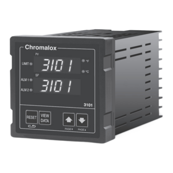
- Page 1 3101 High/Low Limit Controller Operator’s Manual Issue Date 0037-75253 November 2007...
-
Page 2: Table Of Contents
Digital Event Input ............41 Analog Output Option ............ 43 Digital Communications ..........45 Calibration ..............51 Specifi cations ..............57 Troubleshooting .............. 61 Warranty and Return ............63 Appendices PAGE/MENU Tables ............65 Menu Index Index ..................73 Chromalox 3101 Operator's Manual... - Page 3 Alarm #1 Relay Output ............12 2.14 Alarm #2 Output ..............12 2.15 100-240 Vac Instrument Power Conn. (3101-11**0) .... 13 Front Panel Identifi cation ............. 16 PAGE/MENU Setup Structure ..........17 Sample of PAGE/MENU Table ..........19 Security Levels and PAGE/MENU Contents ......20 Security Codes and View/Adjust Levels ......
- Page 4 RS422/RS485 Communications Switches......46 RS232 Wiring Connections ..........46 RS232 Connector Pin Designations........47 RS485 Wiring Connections (4-wire) ........47 RS422 Connector Pin Designations........48 RS485 Wiring Connections (2-wire) ........48 RS485 Connector Pin Designations........48 Chromalox 3101 Operator's Manual...
- Page 5 Chromalox 3101 Operator's Manual...
-
Page 6: Getting Started
Section 1 Getting Started The Chromalox 3101 is a compact 1/4 DIN program- mable high/low limit controller with two independent alarms. While designed to be low-cost, the 3101 has many features of high-end limit controllers: • Universal Sensor Input • Switching Power Supply allows universal AC voltage input (100 to 230 Vac) •... -
Page 7: Model Identifi Cation
RS422/485 Digital Communications and Alarm #2 Relay—Form C contact, 5A @ 120 or 230 Vac RS232 Digital Communications and Alarm #2 Relay—Form C Contact, 5A @ 120 or 230 Vac Code Power Supply 100 - 230 Vac 3101 - Typical Model Number... -
Page 8: Installation
Temperature extremes and excessive moisture can damage the instrument. Switch The 3101 has up to seven (7) hardware switches Settings located on the bottom of the controller. The switches are accessible through cutouts in the... - Page 9 Figure 2.3. 2. Place the controller through the square panel cutout and replace the mounting clip. 3. Tighten the mounting clip screw (do not overtighten) to secure the controller fi rmly against the mounting surface. Chromalox 3101 Operator's Manual...
-
Page 10: Mounting Dimensions
Figure 2.2 Mounting Dimensions (96) (19) (102) (92) (96) (92) (90) Panel Cutout Measurements are shown in inches. Millimeters are shown in parentheses. Figure 2.3 Mounting Diagram Mounting Hole Mounting Clip Mounting Tab Panel Cutout Chromalox 3101 Operator's Manual... - Page 11 Electrical noise can affect the function of any control system. When driving a contactor coil or other inductive load, an appropriately rated AC snubber circuit is recommended (Chromalox Part. No. 0149-01305), as described on page 11, “Re- lay Output Wiring.”...
-
Page 12: Wiring Terminal Identifi Cation
Figure 2.5. • Three wire RTDs are recommended for greatest accuracy. • Standard shielded copper wire is recommended for RTD extensions. Chromalox 3101 Operator's Manual... -
Page 13: Thermocouple Connections
Chromalox recommends 3-wire RTDs for greatest accuracy, and standard shield- ed copper wire for RTD extensions. Make 3-wire RTD connections to terminals 7, 8 and 9 as shown in Figure 2.6 on the following page. Chromalox 3101 Operator's Manual... -
Page 14: 3-Wire Rtd Connections
It is also necessary to jumper terminals 8 and 9 on the instrument to complete a 2-wire hookup. Figure 2.7 3101 2-Wire Connections Current/Voltage Inputs Figure 2.8 3101 Current Input Wiring (Self-powered) 4-20mA Chromalox 3101 Operator's Manual... -
Page 15: Voltage Input Wiring (Self-Powered)
Figure 2.9 3101 Voltage Input Wiring 1-5 Vdc (Self-powered) 0-5 Vdc The 3101 has a +24 Vdc power supply which can be used to power a 4-20mA transmitter. Figure 2.10 3101 Current +24 Vdc Input Wiring 4-20mA (Loop-powered by controller) -
Page 16: Relay Output Connections
Output The 3101 is supplied with: Wiring • 1 Relay Output for Limit Output Control • 1 Relay Output for Alarm #1 As an option, it may also include: • 1 Relay Output for Alarm #2 ☛ Warning Incorrect output wiring may cause system/pro- cess damage. -
Page 17: Alarm #1 Relay Output
Figure 2.14. Figure 2.14 Alarm #2 Output 3101 Load AC Neutral Normally Open Fuse* Alarm #2 120 or 230 Vac Normally Closed Load AC Neutral * Fuse should be sized for the current of Alarm #2 Output. Chromalox 3101 Operator's Manual... -
Page 18: 100-240 Vac Instrument Power Conn. (3101-11**0)
Instrument Power Wiring Make 120/230 Vac instrument power connections to terminals 16-18 as shown in Figure 2.15. Figure 2.15 3101 100-240 Vac 100 - 240 Vac Instrument Power Neutral Connections (3101-11**0) Chassis Ground Chromalox 3101 Operator's Manual... - Page 19 Chromalox 3101 Operator's Manual...
-
Page 20: Operation
Normal Display Mode. Disable Lower Display The lower display may be disabled for applica- tions where it is desirable to have only the Pro- cess Variable displayed in the upper display. See SET PAGE, menu LDSP, page 24. Chromalox 3101 Operator's Manual... -
Page 21: Front Panel Identifi Cation
• Scrolls through MENUs in Setup Mode VIEW DATA • In Normal Display Mode, pushbuttons adjust Setpoint. Pushbutton • To access Display Page • In Setup Mode, pushbuttons increase/decrease MENU • To scroll through Display values. Page Menus Chromalox 3101 Operator's Manual... -
Page 22: Page/Menu Setup Structure
PAGE/MENU All control parameters, selections and calibration Setup procedures for the 3101 are accomplished through simple MENU selections. These MENU selections are organized into PAGES. On each PAGE you will fi nd a specifi c set of related functions. This organization allows you to go directly to the parameter to be adjusted, without stepping through a long series of unrelated entries. - Page 23 MENU will appear on the upper display, and the current value will appear in the lower display. AL 1 ALO1 AHI1 ➮ ➮ PAGE ▲ ▼ ▲ ▼ ▲ ▼ VIEW VIEW VIEW RESET RESET RESET DATA DATA DATA Chromalox 3101 Operator's Manual...
-
Page 24: Sample Of Page/Menu Table
Process Variable P P P P P ROC Controller Type C C C C C ONT H H H H H I I I I I L L L L L O O O O O Chromalox 3101 Operator's Manual... -
Page 25: Security Levels And Page/Menu Contents
Security Every parameter or selection in the 3101 control- Levels ler’s setup PAGEs has an identifying MENU. Each MENU is assigned one of four Security Levels, A-D. In each level you may view certain MENUs, and adjust certain MENUs. This allows you to... -
Page 26: Security Codes And View/Adjust Levels
LOCK on the SET PAGE, adjustment of all parameters is locked out. An additional security number can be added using the menu for User Selectable Security Code (SET PAGE, menu CODE). Chromalox 3101 Operator's Manual... - Page 27 3. To reset the menus Time Over Setpoint timer (TOSP) and Peak Temperature Displays (PEAK), RESET press while the menus are displayed. 4. To exit the Display Page, press and hold RESET for 3 seconds. Chromalox 3101 Operator's Manual...
-
Page 28: Controller Setup Pages
Digital Communications Throughout the following Setup PAGEs you will More fi nd these symbols . This indicates a section Info of this User’s Manual where more specifi c infor- mation on a parameter/application/feature can be found. Chromalox 3101 Operator's Manual... - Page 29 458-735 = Security level C 736-999 = Security level D Ambient Temperature Low -3 to 153 A LO Ambient Temperature High -3 to 153 A HI Lower Display Disable ON = Enabled LDSP OFF = Disabled Chromalox 3101 Operator's Manual...
- Page 30 INLO Input high INHI DONE = Calibration fi nished Analog Output Zero 0 to 4095 AO 0 Calibration Analog Output Span 0 to 4095 AO S Factory Calibration Recovery Ready RECC Wait ---- DONE = Finished Chromalox 3101 Operator's Manual...
- Page 31 Alarm 1 Low Setpoint Instrument Sensor Span ALO1 Alarm 1 High Setpoint Instrument Sensor Span AHI1 Output 1 Dead Band 0 to 100°F (Alarm Hysteresis) (.00 to 6.25% of span for analog inputs) Alarm 1 Inhibit INH1 Chromalox 3101 Operator's Manual...
- Page 32 Alarm 2 Low Setpoint Instrument Sensor Span ALO2 Alarm 2 High Setpoint Instrument Sensor Span AHI2 Output 2 Dead Band 0 to 100°F (Alarm Hysteresis) (.00 to 6.25% of span for analog inputs) Alarm 2 Inhibit INH2 Chromalox 3101 Operator's Manual...
- Page 33 Chromalox 3101 Operator's Manual...
-
Page 34: Limit Control Operation
Section 5 Limit Control Operation Limit The 3101 High/Low Limit Controller provides con- Control trol output and visual indication when the process Operation variable exceeds the limit setpoint. The control- ler can be setup to operate as a high or low limit controller at the “controller type”... - Page 35 (see Figure 5.1 on the following page). Power Down Recovery: In the event of a power failure, the 3101 will re- tain the current status of the Limit Alarm, record the Time Over Setpoint (TOSP) and Peak Tem- perature value (PEAK).
-
Page 36: Process Variable Profi Le-High Limit Control
Limit When the process variable exceeds the limit setpoint, the relay output is de-energized and the Limit LED comes ON. The Limit Alarm cannot be reset until the process variable falls below the Limit Setpoint Deadband. Chromalox 3101 Operator's Manual... - Page 37 Alarm Acknowledge Switch. The digital input function is setup on the SET PAGE, menu ENTI. See page 41 for details. Over The 3101 is equipped with a timer to register the Setpoint total process time over setpoint. This internal tim- Timer er begins recording the total time of the process over (or under) the limit setpoint.
- Page 38 Peak The 3101 also records and displays the peak Temperature (minimum or maximum) temperature when the Display process variable exceeds the setpoint. VIEW DATA To see the PEAK temperature, press access the PEAK menu: DISP PEAK PEAK ➮ ➮ PAGE ▲...
- Page 39 Chromalox 3101 Operator's Manual...
-
Page 40: Alarms
Section 6 Alarms The 3101 controller has one alarm output (Alarm #1) and an optional Alarm #2 output. The optional Alarm #2 output is indicated by the following model numbers: Optional Outputs Model Number Alarm #2 3101 - 11*1* 3101 -... -
Page 41: Low Alarm Inhibit
Alarm Inhibit is selectable (ON/OFF) for each alarm output. INH2 ▲ ▼ RESET VIEW DATA Temperature Figure 6.1 Low Alarm Power Inhibit Normal Temperature Alarm Deadband Lo Alarm Setpoint Process Variable Lo Alarm Inhibit Lo Alarm Cleared Chromalox 3101 Operator's Manual... - Page 42 The alarm cannot be re- set until the process is out of the alarm condition. The Digital Input provides a remote alarm reset button (see page 41). ENTI RESET VIEW ▲ ▼ DATA Chromalox 3101 Operator's Manual...
- Page 43 Alarm 1 Low Setpoint Instrument Sensor Span ALO1 Alarm 1 High Setpoint Instrument Sensor Span AHI1 Output 1 Dead Band 0 to 100°F (Alarm Hysteresis) (.00 to 6.25% of span for analog inputs) Alarm 1 Inhibit INH1 Chromalox 3101 Operator's Manual...
- Page 44 Alarm 2 Low Setpoint Instrument Sensor Span ALO2 Alarm 2 High Setpoint Instrument Sensor Span AHI2 Output 2 Dead Band 0 to 100°F (Alarm Hysteresis) (.00 to 6.25% of span for analog inputs) Alarm 2 Inhibit INH2 Chromalox 3101 Operator's Manual...
- Page 45 Chromalox 3101 Operator's Manual...
-
Page 46: Digital Event Input
Section 7 Digital Event Input The 3101 controller Digital Event Input allows you to use a pushbutton contact to function as a remote Alarm Reset. The external switching device is connected to the controller Digital Input at terminals 1 and 2 (see page 10 for wiring instructions). - Page 47 Chromalox 3101 Operator's Manual...
-
Page 48: Analog Output Option
The Analog Output Option is provided on control- Output lers with model number Option • 3101 - 111** This option can be used to transmit process variable to a remote recorder, computer or other device via a 4-20mA or 1-5Vdc signal, selectable by a switch on the bottom of the controller. -
Page 49: Process Output Wiring
500°F = 20mA). SCAL PAGE VIEW ▲ ▼ RESET DATA Custom Scaling Page MENU Description Available Settings Security Analog Process Instrument Sensor Span AOTL Output - Low Analog Process Instrument Sensor Span AOTH Output - High Chromalox 3101 Operator's Manual... -
Page 50: Digital Communications
User’s Manual provided with the software. Hardware Setup RS232 can be used to connect a computer or mo- dem to a single 3101 controller. RS232 lines can be run over distances up to 50 feet. RS422 and RS485 provide multidrop network... -
Page 51: Rs422/Rs485 Communications Switches
Wiring connections for the digital communica- tions interface are made on terminals 9-13 using shielded serial interface cable. RS232 Communications 3101 Computer Figure 9.2 RS232 Wiring Connections Note: The DTR output is always enabled when the 3101 power is on. Chromalox 3101 Operator's Manual... -
Page 52: Rs232 Connector Pin Designations
Figure 9.4 RS422A Wiring Connections (4-wire) 3101 3101 XMT- XMT+ RCV- RCV+ XMT- XMT+ RCV- RCV+ Computer with RS422 Interface Card XMT+ XMT- RCV+ RCV_ Note: 270 resistors recommended across receive line on computer and last controller. Chromalox 3101 Operator's Manual... -
Page 53: Rs422 Connector Pin Designations
Card R/T+ R/T- Note: 270 resistors recommended across receive line on computer and last controller. Figure 9.7 DB - 9 DB - 25 RS485 R/T + R/T + Connector Designations R/T - R/T - (Typical) Chromalox 3101 Operator's Manual... - Page 54 Mode Selection Disabled DIGT Computer Interface CPIF ASCII Line* LINE Baud Rate 1200 BAUD 2400 4800 9600 19.2K Address 1 to 255 ADDR *For ASCII Line Mode Communications, see page 65 for PAGE # / MENU #. Chromalox 3101 Operator's Manual...
- Page 55 Chromalox 3101 Operator's Manual...
-
Page 56: Calibration
Instructions are also given for: • Factory Calibration Recovery • Calibration Offset When is The 3101 controller is factory calibrated before Calibration shipment to you, therefore, it is not necessary to Required? calibrate the controller when you receive and in- stall it. - Page 57 4. To access the calibration, you will need to be at LEVEL D security. Enter Security Code “736” at menu LOCH on the SET PAGE. Sensor The sensor input of the 3101 can be calibrated Input using an appropriate sensor simulator and the Calibration Sensor Calibration menu on the Input Page.
- Page 58 Sensor maximum ranges are: Sensor °F °C J T/C 1400 K T/C 2400 1316 1100 3200 1760 3200 1760 3300 1816 293.49 4-20mA 20mA 0-5 Vdc 5 Vdc 1-5 Vdc 5 Vdc Chromalox 3101 Operator's Manual...
- Page 59 2. Go to menu AO O. Adjust the value in the lower display—using —until the meter reads 4mA or 1.000 Vdc. AO O RESET VIEW ▲ ▼ DATA Chromalox 3101 Operator's Manual...
- Page 60 The Factory Calibration Recovery should be used as a “starting point” for recalibration, should the unit become severely out of calibration. Factory Calibration Recovery is performed on the INPT PAGE, menu RECC. RECC ▲ ▼ RESET VIEW DATA Chromalox 3101 Operator's Manual...
- Page 61 To establish the calibration offset: 1. Go to menu COFF on the Input Page. COFF ▲ ▼ VIEW RESET DATA 2. Use to set the calibration offset, adjustable from -100 to 100°F. COFF RESET VIEW ▲ ▼ DATA Chromalox 3101 Operator's Manual...
-
Page 62: Specifi Cations
Process Variable Output Signal 4-20mA into 0-800 load 1-5 Vdc into 100K or greater load Selectable via DIP switch Range Programmable over selected sensor span for retransmission of Process Variable Accuracy ±0.2% of programmed span, ±1 LSD Chromalox 3101 Operator's Manual... - Page 63 Depth Behind Projection 4.00 inches (102 mm) Front Panel Projection 0.75 inches (19 mm) Panel Cutout 3.6 x 3.6 inches (92 mm x 92 mm) Case Material High Impact, Black ABS Plastic Front Panel NEMA 4X Construction Chromalox 3101 Operator's Manual...
- Page 64 +3°F for 1000 Ft. of 18 AWG extension wire B Thermocouple +6°F for 1000 Ft. of 18 AWG extension wire T Thermocouple +1°F temperatures > -112°F (-80°C) +2°F temperatures < -112°F (-80°C) RTD, 4-20mA, 1-5 Vdc ±0.1% of Sensor Span/20 bbalanced leadwire resistance Chromalox 3101 Operator's Manual...
- Page 65 Chromalox 3101 Operator's Manual...
-
Page 66: Troubleshooting
Troubleshooting The following Troubleshooting Guide gives simple solutions to common problems, and explains the 3101’s Error Messages. Should you have a prob- lem with your controller, it is a good idea to check this Guide for possible corrections before contact- ing the factory. - Page 67 Chromalox 3101 Operator's Manual...
-
Page 68: Warranty And Return
Chromalox are warranted only to the extent and in the man- ner that the same are warranted to Chromalox by Chromalox’s vendors, and then only to the extent that Chromalox is reasonably able to enforce such... - Page 69 Upon buyer’s submission of a claim as provided above and in its substantiation, Chromalox shall at its option either (i) repair or replace its Prod- ucts, parts or work at the original f.o.b. point of delivery or (ii) refund an equitable portion of the purchase price.
-
Page 70: Page/Menu Tables
Digital Comm. Mode Selection P6/M1 Baud Rate P6/M2 Address P6/M3 * For digital communications using the Ascii Line Mode, you will use PAGE#/MENU# instead of the alphanumeric cues. For example, Alarm 1 Low Setpoint would be P4/M4. Chromalox 3101 Operator's Manual... - Page 71 Settings for: Limit Control Alarms Input Digital Communications Calibration Digital Input Analog Process Output Security Codes Security Security Adjust Security Codes Level Code Level - - - A, B A, B, C A, B, C, D Chromalox 3101 Operator's Manual...
- Page 72 123-457 = Security level B 458-735 = Security level C 736-999 = Security level D Ambient Temp Low -3 to 153 Ambient Temp High -3 to 153 Lower Display ON = Enabled LDSP Enable OFF = Disabled Chromalox 3101 Operator's Manual...
- Page 73 Input high INHI DONE = Calibration fi nished Analog Output Zero 0 to 4095 AO 0 Calibration Analog Output Span 0 to 4095 AO S 3902 Factory Calibration RDY Ready RECC Recovery Wait ---- DONE = Finished Chromalox 3101 Operator's Manual...
- Page 74 Alarm 1 Low Setpoint Instrument Sensor Span Span Low ALO1 Alarm 1 High Setpoint Instrument Sensor Span Span High AHI1 Output 1 Dead Band 0 to 100°F 1°F (Alarm Hysteresis) (.00 to 6.25% of span for analog inputs) Alarm 1 Inhibit INH1 Chromalox 3101 Operator's Manual...
- Page 75 Alarm 2 Low Setpoint Instrument Sensor Span Span Low ALO2 2 High Setpoint Instrument Sensor Span Span High AHI2 Output 2 Dead Band 0 to 100°F 1°F (Alarm Hysteresis) (.00 to 6.25% of span for analog inputs) Alarm 2 Inhibit INH2 Chromalox 3101 Operator's Manual...
- Page 76 Digital Communications Page: DIG PAGE MENU Description Available Settings Factory Settings Security Mode = Disabled DIGT CPIF Selection CPIF = Computer Interface LINE = ASCII Line Baud Rate 1200 BAUD 19.2K 2400 4800 9600 19.2K Address 1 to 255 ADDR Chromalox 3101 Operator's Manual...
- Page 77 Chromalox 3101 Operator's Manual...
-
Page 78: Index
Dimensions ..................5, 58 Dip Switches ..................3 Analog Output Signal ..............43 RS422/RS485 Communications Switches ........46 Sensor Input Switches ..............4 Displays ...................15-19, 24 Display Mode, Normal ..............15, 16 Error Messages .................. 61 Chromalox 3101 Operator's Manual... - Page 79 Setup ................. 20, 24, 41 Peak Ambient Temperature Display ........... 33 Peak Temperature Display ..............33 Pushbuttons ..................15-19 Repair ....................63 Reset Pushbutton ................. 16, 18 RTD Inputs ..................52 Calibration ..................52 Wiring ....................9 Chromalox 3101 Operator's Manual...
- Page 80 RS232 Connector Pin Designations ..........47 RS422A Wiring Connections (4-wire) ..........47 RS422A Connector Pin Designations ........... 48 RS485 Wiring Connections (2-wire) ..........48 RS485 Connector Pin Designations ..........48 Terminal Identifi cation ..............7 Voltage Input Wiring (Self-powered) ..........10 Chromalox 3101 Operator's Manual...
- Page 81 Chromalox 3101 Operator's Manual...
- Page 82 1382 HEIL QUAKER BLVD., LAVERGNE, TN 37086 Phone: (615) 793-3900 www.chromalox.com...
Need help?
Do you have a question about the 3101 and is the answer not in the manual?
Questions and answers