
Related Manuals for Chromalox CET-GF


Summary of Contents for Chromalox CET-GF
- Page 1 Installation Instructions CET-GF for use with Self-Regulating & Constant Wattage Electric Heating Cables PJ971 161-562581-344 January, 2023...
-
Page 2: Certifications & Approvals
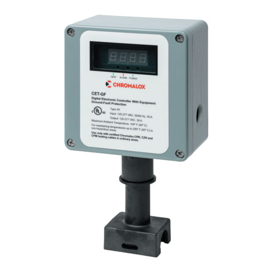
Pipe Standoff Protective Sleeve General Certifications & Approvals The CET-GF unit is used for temperature control and electrical termination of self-regulating and constant wattage electric heating cables. Each kit contains the terminations needed to make all electrical connections. The CET-GF digital thermostat kit is a microproces-... -
Page 3: Precautions And Warnings
Equipment) may result in injury or even death. plication without a complete re-evaluation by the man- Chromalox will not be liable for failure of customer to ufacturer. The operator shall ensure these instructions adhere to governing standards. -
Page 4: General Warnings
The consequences sult in equipment damage, operating losses, of all possible failure modes must be evalu- injury, or death. Chromalox will not be liable ated. for failure to adhere to all governing regula- tions, codes, standards, site procedures and Dommages matériels. - Page 5 NOTICE/AVIS NOTICE/AVIS If the equipment is used in a manner not speci- Tools should not be used to depress the push- fied by the manufacturer, then the warranty buttons on the inner cover. will be invalidated. Il ne faut pas utiliser d’outils pour appuyer sur Si l’équipement est utilisé...
-
Page 6: Start-Up & Commissioning
Start-up & Commissioning Installation review, Start-up, and Commissioning shall NOTICE/AVIS only be performed by Chromalox personnel. Other- Inspect the equipment/system to ensure no wise, the User assumes all responsibilities, and all war- damage has occurred within 48 hours of re- ranties, both written and implied, are voided otherwise. - Page 7 Strap pipe stand- to the end of heating cable and remove the outer off to pipe with pipe strap (Chromalox type PS not jacket from the cable. WARNING: DO NOT CUT included) and attach extra cable to pipe as appro- METAL BRAID.
- Page 8 5. Score the inner insulation 6 inches from the end. 6. Use tin snips or similar tool to cut excess material Lightly cut the inner jacket up the center to end of from between the buss wires. heating cable and remove the inner jacket from the *Separate CZH leads and strip 1/4”...
- Page 9 Compression Fitting Locknut Grommet O-Ring 9. Slide compression fitting over cable. Grommet 10. Seat O-Ring into compression fitting groove at should be placed inside pipe standoff. Termination base of threads. Ensure O-Ring is not twisted. boot should be spaced 1/2” from sealing grommet. Assemble junction box to compression fitting as Tighten compression fitting until it bottoms out shown.
- Page 10 er ONLY until snug. It is recommended that the DANGER/DANGER lid be secured to the torque specified in the Hazardous voltage enclosed. Contact will installation manual. Overtightening or uneven cause electric shock and burn. Do not operate tightening may cause the lid to break which thermostat if lid is cracked, broken or uneven would void all environmental approvals.
- Page 11 NOTICE/AVIS Mettez tous les équipements hors tension avant d’ouvrir les boîtes de jonction et les pan- Refer to the Chromalox unit design drawing neaux de commande et suivez les procédures for specific certifications(s) and/or classifica- de verrouillage et d’étiquetage appropriées.
-
Page 12: Connecting Power To The Unit
Connecting RTD Wire Alarm Wiring 1. Connect RTD wire according to the schematic: The alarm on the CET-GF unit is an electromagnetic mechanical relay. The alarm relay is a dry contact and will need separate AC or DC voltage supplied. See page 15 for alarm contact ratings. -
Page 13: Troubleshooting
FALSE. * Heat is turned OFF. Should the ground fault con- dition clear after that, the CET-GF would then go back to normal operation, switching the heat ac- Resetting GFEP alarm (only when latch cording to temperature setting. - Page 14 Optional Wall Mount Kit The CET-GF may be mounted on vertical surfaces. . Considerations: Ordering Information: 1. The kit comes complete with two stainless steel Wall Mount Kit PCN (Part Number): 514220 mounting brackets and the necessary hardware to mount the brackets to the CET-GF.
-
Page 15: Agency Approvals
Product Maintenance & Care Settings: The following inspections should occur upon receipt of product and at least once every year. Setpoint: 32°F(0°C) to 200°F(93°C) Alarms: High temp to 230°F (110°C) a. Wiring Low temp to 75°F (24°C) Inspect wiring for wear, fraying and evidence of Deadband: 2°F(2°C) to 10°F(6°C) overheating. - Page 16 Limited Warranty: Please refer to the Chromalox limited warranty applicable to this product at http://www.chromalox.com/customer-service/policies/termsofsale.aspx. Chromalox 103 Gamma Drive Pittsburgh, PA 15238 (412) 967-3800 www.chromalox.com © 2021 Chromalox, Inc. All rights reserved.
Need help?
Do you have a question about the CET-GF and is the answer not in the manual?
Questions and answers