Table of Contents
Advertisement
Quick Links
Advertisement
Table of Contents

Related Manuals for Chromalox ChromaFP Series


Summary of Contents for Chromalox ChromaFP Series
- Page 1 Installation & Operation Manual ChromaFP Series PK568 April 2023...
-
Page 2: Table Of Contents
Table of Contents Section Page Introduction ............................6 Chroma-FP Installation notes ......................7 Wiring the Chroma-FP1, Chroma-FP1-MDB (120V) ................8 Wiring the Chroma-FP2, Chroma-FP2-MDB (240V) ................9 Operating instructions ........................10 Turning the system ON and OFF ..................... 11 Selecting temperature scale ......................11 Selecting Automatic or Manual mode ..................... - Page 3 Safety Precautions Before Powering Up Chromalox takes great pride in knowing that we have provided to you a product of premium quality and IMPORTANT SAFEGUARDS workman-ship. We have taken every precaution to ensure that your equipment arrives safe and secure.
-
Page 4: Introduction
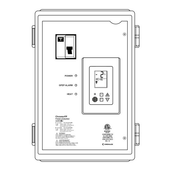
Introduction Chroma-FP Series Installation The Chroma-FP offers various operating and programming options such as: The Chroma-FP Series power boxes offer smart PLEASE READ THIS MANUAL AND THE SAFETY WARNINGS CAREFULLY BEFORE • Switchable temperature scales (°F or °C) and easy control for HEAT TRACING SYSTEMS. INSTALLING AND USING THE CONTROLLER AND SAVE IT FOR FUTURE USE. - Page 5 Indication Indication Supply Supply Dry Contact Dry Contact 240 VAC 120 VAC (NO/NC) (NO/NC) CS-HL CS-HL *See table *See table (By Chromalox) (By Chromalox) Heater Heat Heater Heat Load Indication Load Indication Branch circuit protection Branch circuit protection Aquastat (24VAC)
-
Page 6: Operating Instructions
Connecting FPC-02-OD-AB Slaves (Option) Operating Instructions Turning the System ON and OFF Number of FPC-02-OD Slaves Master’s MAC Addresses Slave’s MAC Addresses 1. Press and hold the [ON] button for 0.5 Up to 3 1-63 14-16 seconds to turn the system ON or OFF. These slaves should be connected directly to A2,B2 terminals on the PYROCON19 thermostat 2. -
Page 7: Heater Indication
Operating Instructions Technician Settings (Cont.) Use the technician settings mode to view and adjust the following parameters: Heater Indication Number of FPC-02-OD Slaves/Master’s MAC Addresses Heater ON Heater ON Heater OFF Heater OFF Black icon – Heater ON Heater ON Heater ON Heater OFF Heater OFF... -
Page 8: P01 - Temperature Set Point
Technician Settings (Cont.) P03 – Time delay before stopping the heater 1. Press the [SELECT] and [+] buttons Parameters: simultaneously. P01 - Temperature set point 2. “P03”, “dL” and the time delay before 1. Move DIP switch S1 located on the side of stopping the heater (Hold ON) will appear thermostat to ON position. -
Page 9: P07 - Not In Use
Technician Settings (Cont.) P09 – Test conditions mode / Technician commissioning mode P06 – Enable/Disable Temperature sensor / Turn ON test conditions to check the functionality Aquastat logic of the system regardless of temperature sensors parameters (i.e. during the summer). 1. -
Page 10: P15 - Temperature Sensor Calibration Offset
Technician Settings (Cont.) DIP switch S2 - Short measuring times (test only) P15 – Temperature sensor calibration offset Use DIP switch S2 to short the measuring times as follows: 1. Press the [SELECT] and [+] buttons simultaneously. • “ON” - Short measuring times – for test/ S3 OFF, commissioning only (measuring times will 2. -
Page 11: Temperature Sensor Not Connected Or Short Circuit
Temperature Readings and GFEP Communication Errors The GFEP is designed to protect circuits by sensing when a ground fault or Temperature Sensor Readings is earth leakage is greater than 30mA and Out of Reliable Measuring Range automatically open the circuit. •... - Page 12 Object List - Modbus (FPC-02-OD-AB only!) Object List - BACnet (FPC-02-OD-AB only!) Use DIP switch S6 located on the side of thermostat Use DIP switch S6 located on the side of to select BMS (A,B) network protocol - S6 OFF – thermostat to select BMS (A,B) network Modbus protocol - S6 ON –...
- Page 13 Limited Warranty: Please refer to the Chromalox limited warranty applicable to this product at http://www.chromalox.com/customer-service/policies/termsofsale.aspx. Chromalox, Inc. 1347 Heil Quaker Boulevard Lavergne, TN 37086 (615) 793-3900 www.chromalox.com © 2023 Chromalox, Inc.
Need help?
Do you have a question about the ChromaFP Series and is the answer not in the manual?
Questions and answers