
Related Manuals for Chromalox IntelliTrace ITC 1


Summary of Contents for Chromalox IntelliTrace ITC 1
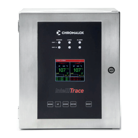
- Page 1 Installation & Operation Manual ITC 1 & 2 Circuit Heat Trace Controller Line or Ambient Sensing Ordinary Areas & Class I, Division 2 PK509-10 0037-75516 June 2018...
-
Page 2: Table Of Contents
Table of Contents Section Page Table of Contents ..............................2 Safety Precautions ..............................3 Introduction ................................4 Model Overview ............................... 5 Theory of Operation ..............................6 Before Powering Up ..............................6 Installation ................................7 Operating the ITC ..............................8 HMI (Human – Machine Interface) ........................8 Main Window .............................. -
Page 3: Safety Precautions
Please read all instructions before operating your sibility of the user, Chromalox will be glad to intelliTRACE ITC1 or ITC2 Heat Trace Controller. -
Page 4: Introduction
• High Resolution TFT Display: malox for premiere quality and innovative solutions for • 2 Circuits displayed / screen (on 2 Circuit unit) industrial heating applications. Chromalox manufac- • Displayed Parameters: Process Variable, Set tures the world’s largest and broadest line of electric Point Temperature, Control Mode, Soft Start sta- heat and control products. -
Page 5: Model Overview
Model Overview The ITC series IntelliTRACE Controller is designed The ITC2 may also be used as a 2-channel ambient for industrial Heat Trace Line and/or Ambient Sens- sensing controller that uses only one RTD to control ing applications in Hazardous (Class I, Division 2) or both circuits. -
Page 6: Theory Of Operation
3. Alarm, latching – No change in output. Before Powering Up Wiring and Connections Chromalox takes great pride in knowing that we have provided to you a product of premium quality and Check wiring and connections as follows: workmanship. We have taken every precaution to en- a. -
Page 7: Installation
All debris a manner not specified by Chromalox, the pro- must be removed from the heat sink fins. High pressure tection provided may be impaired. This could... -
Page 8: Operating The Itc
Operating the ITC HMI (Human – Machine Interface) There are three areas on the front panel of the ITC in which the User may visually receive information or pro- vide input to the controller: 1. LED status indication for Power, Load &... -
Page 9: Navigating The Itc
Navigating the ITC Visually, here is how one navigates through the ITC Menus & Parameters: Security Level 3 Security Level 2 Security Level 1 1. Main Window 2. Login Logged? Correct? Mode Mode Mode Mode Mode 3. Temperature Menu 4. Current Menu 5. -
Page 10: The Keypad
The Keypad The function of each key is as follows: There are five capacitive touch keys or buttons on the front panel. The keypad allows the user to select or FUNCTION change parameters & settings, clear alarms and navigate throughout the ITC programming areas. See Figure 3 Allows the user to Navigate between MODE shown below:... -
Page 11: Security Levels
Security Levels You must first enter a passcode that is aligned with the You will be returned to the main screen if no buttons menu that you wish to access. In most cases, limited are depressed within a 30 second time frame. access to certain programming areas is desired. -
Page 12: The Current Menu
The Current Menu Security Levels 2 & 3 4. Current Menu Lower limit of the Load Current Variable at which the system goes into alarm state. Current This alarm may be turned OFF by going Alarm one increment beyond the Lowest setting. Upper limit of the Load Current Variable at High which the system goes into alarm state. - Page 13 The Control Menu provides access to the types of Automatic Control, Mode of Operation, the parameters which influence the control algorithms and the Soft Start function: Auto Control Mode, Auto/Manual/Off Control, Dead- band, Autotune, Proportional Band, Integral, Rate (Derivative), Soft Start function and Manual Offset. 5.
-
Page 14: The Soft Start Function
The Soft Start Function The Soft Start function is located within the Control Menu page. The Soft Start function will operate inde- pendently on each circuit. To limit inrush current on the overall system, an inher- ent characteristic of self-regulating/limiting heating ca- ble, a proprietary Soft Start algorithm is applied during system start-up. - Page 15 6. Comms Menu Data transmission speed in Serial Communications, in Hertz (Hz). Baud Rate The range offered by the ITC is 2.4k, 4.8k, 9.6k, 19.2k, 38.4k, 56.0k Parity The parity bit is to be set to NONE, EVEN or ODD. This is the Identification or Address of the ITC Unit on a Modbus Network.
- Page 16 4. Use the DOWN or UP keys to highlight IP AD- a. The IP ADDRESS is composed of four fields, DRESS, then press ENTER key to edit the IP Ad- each with a value range from 0 to 255. dress: b.
- Page 17 The Systems Menu Security Level 3 The System Menu provides access to system information and system settings for the ITC. Items contained in the System Menu include: Firmware Version of the ITC, Button Sound for Keypad interaction, Units (Temperature), Tem- perature Sensing Type, Failed Sensor Output, (Security) Password for Levels 1, 2 &...
-
Page 18: The System Menu
The ITC accepts up to two RTD inputs per channel. In Auto Control Mode, the output of each circuit will function according to the Temp Sensing Setting. However, when in Manual Mode, the Output will only consider the Output % as selected by the User. The following settings and their respective function are available when in AUTO Mode: •... -
Page 19: Current Sampling
Current Sampling All active loops are individually tested for 2 seconds and a new GFEP current is automatically and continu- every 2 minutes. During the test, a current load value is ously calculated. The Yellow Load LEDs will be illumi- updated on the yellow bar located on the Main Window nated during the sampling test. -
Page 20: Dimensions
Dimensions Inch 11.8 316 SS Enclosure 30.2 25.1 19.4 ITC Controller Inch 10.3 Fiberglass Enclosure 26.2 21.3 19.7 Mounting Brackets Heat Sink Wall Mount Brackets 8.750/10.625 (22.2/27.0) 8.250/10.188 (21.0/25.9) .218 (0.55) .390 (0.99) .875 (2.2) 10.000/11.813 (25.4/30.0) Dimensions are given for both enclosure types: Fiberlgas/316SS Wall Mount Bracket Dimensions are in Inches Wall Mount Bracket Dimensions are in Inches (cm) -
Page 21: Default Settings
Default Settings Below is the ITC parameter settings chart organized by Menu Screen. It includes the default, minimum, maximum and / or the range of settings, where applicable. The chart is for either 1 or 2 circuit units. Parameter Defaults, Min., Max. & Range & User Settings Screen Menu &... - Page 22 Parameter Defaults, Min., Max. & Range & User Settings Screen Menu & Parameter 6. Comms Menu Default Min. Max. Also User Settings Baud Rate 9.6k 2.4k, 4.8k, 9.6k, 19.2k, 38.4k, 56.0k Parity None Even None ModBus ID IP Address Optional Feature DHCP Do Not Use 7.
-
Page 23: Specifications
Specifications Input 3-wire RTD, 100 W PT, 0.00385 W/W/˚C, 20 W balanced lead wire Sensor Type Number of Sensor Inputs 1 or 2 per Circuit Sensing Configuration Range: Single, Low, High, Average Output Power Switching Number of Circuits 1 or 2 Capacity 40 Amps per Circuit (Breaker size shall be 50 Amps maximum per circuit or 125% of anticipated load) - Page 24 Alarms Alarm Types Low & High Temperature, Low & High Current, High GFEP, Sensor Failure Alarm Relays 1 x DC Alarm Output, 1.8 Amp, Customer Supplied 0 - 50 VDC 1 x AC Alarm Output, 1.8 Amp, Customer Supplied 12-240 VAC Mode Default Optional...
-
Page 25: Equipment Ratings
Equipment Ratings Field Wiring Considerations Voltage Rating: ......100-277 VAC, 50/60 Hz Current Rating: ......40 amps per Circuit Torque values for line/load wiring Number of Circuits ..........1 or 2 terminals: ..........10-13 in/lbs. (1.1-1.5 N-m) Ambient Temperature Rating: ....-40°F to +104°F (-40°C to +40°C) Torque values for RTD 1 &... -
Page 26: Customer Wiring
Customer Wiring Power, Heater, Alarms & Sensors These connections are facilitated via the main ITC Board(s) RTD 2A RTD 2B SENSOR INPUTS Circuit 2 – Main ITC Board – AC INPUT 100-277 VAC Breaker must be rated at 125% of max heater load, but not to exceed 50 Amps... - Page 27 Communications These connections are facilitated via the Display Board. Modbus TCP/Ethernet or Web Server/Ethernet (when ordered) uses the RJ45 connector Display Modbus RTU/RS485 or /RS422 use the Board Green Terminal Blocks (Detail Below) RS485 2-Wire RS422 4-Wire Use RX+, RX-, TX+ & TX- Must Jumper (RX+/TX+) &...
-
Page 28: Modbus Serial Communications
Modbus Addendum Modbus Serial Communications A message for either a QUERY or RESPONSE is made up of an inter-message gap followed by a sequence of The ITC supports Modbus serial communications. For data characters. The inter-message gap is at least 3.5 a complete description of the Modbus protocol refer to data character times. - Page 29 Description of Modbus Register Set Modbus defines several function types; these instruments support the following types: Table 1 - Modbus Function Code Set Function Code Function Name Read Holding Registers Read Input Registers Write Single Holding Register Write Multiple Holding Registers Input Registers Table 2 - ITC-FS 1&2 Circuit Input Registers Address...
- Page 30 Holding Registers Table 3 - ITC-FS 1&2 Circuit Holding Registers Address Description Range Comments 40000 Units 0-F; 1-C 40001 Setpoint Circuit 1 -80-1100 Expressed as an integer number 40002 Setpoint Circuit 2 -80-1100 Expressed as an integer number 40003 Control Mode for Circuit 1 0=PID;...
- Page 31 Address Description Range Comments 0 - NONE 40022 Parity 1 - EVEN 2 - ODD 40023 Modbus Slave Address 0-255 Expressed as an integer number 40024 Reserved GFEP Alarm Threshold for Expressed as an integer number 40025 30-150 Ckt 1 (in mA e.g.
-
Page 32: Service Contact Information
Chromalox, Inc. 103 Gamma Drive Pittsburgh, PA 15238 Phone: (412) 967-3800 Customer Service Hotline: 1-800-443-2640 Limited Warranty: Please refer to the Chromalox limited warranty applicable to this product at http://www.chromalox.com/customer-service/policies/termsofsale.aspx. Chromalox, Inc. 1347 Heil Quaker Boulevard Lavergne, TN 37086 (615) 793-3900 www.chromalox.com...
Need help?
Do you have a question about the IntelliTrace ITC 1 and is the answer not in the manual?
Questions and answers