
Subscribe to Our Youtube Channel
Related Manuals for Chromalox C4


Summary of Contents for Chromalox C4
- Page 1 Hardware Instruction Manual 4-Channel SCR Power Controller with Independent PID Control PK544 0037-75573 April 2018...
-
Page 2: Table Of Contents
Table of Contents Important Safeguards ......................1 1. Initial Instructions ......................2 1.1 General Description ..........................2 1.2 Features ..............................2 1.3 Product Inspection ..........................2 2. Dimensions & Weights ...................... 3 3. Installation - Mounting ...................... 4 4. Installation - Wiring ......................5 5. -
Page 3: Important Safeguards
Important Safeguards This controller utilizes a heat sink which is de- HIGH VOLTAGE (up to 480 VAC) is used in the signed to cool the unit during operation. Un- operation of this equipment; DEATH ON CON- der no circumstance should air flow around the TACT may result if personnel fail to observe controller be compromised in any way. -
Page 4: Initial Instructions
Chromalox representative immediately. • Food Processing Read through all installation sections in detail within this document before installing the C4 on any piece of equipment or in a control panel enclosure. Spacing re- 1.2 Features quirements must be honored for proper operation and •... -
Page 5: Dimensions & Weights
2. Dimensions and Weights Models without Fuse Holder 0.16 0.75 0.16 (101.5) (19.6) (35) (140) (132) (140) 3.85 (92.5) (140) (109.5) 5.75 (147) 1.55 0.75 (101.5) (42) (140) (19.5) 0.16 0.16 (111.5) (35) 5.75 (147) (132) (140) 3.65 (92.5) 3.25 (182) (109.5) (155) -
Page 6: Installation - Mounting
Mounting C4 Models to be installed on a DIN Rail . Rear panel dimensions are on previous page. To remove from DIN Rail: To install C4 onto a DIN Rail: 1. -
Page 7: Installation - Wiring
4. Installation – Wiring This section covers the C4 wiring installation instruc- • Electronic instrumentation and electromechanical tions for the power supply, inputs, outputs and inter- power devices such as relays, contactors, solenoids, faces. etc., MUST ALWAYS be powered by separate lines. -
Page 8: Emission, Immunity And Safety Standards
Per UL, the SCCR (Short Circuit Current Rating) is 100kA for models: C4 - XXXXX - 0 - XX Suitable for use on a circuit capable of delivering not more than 100RMS kA symmetrical, 480VAC when protected only by listed cartridge fuses manufactured by BUSSMAN type DFJ200 non renewable (JDDZ) 200A class J current limiting fuses. -
Page 9: Controller Overview
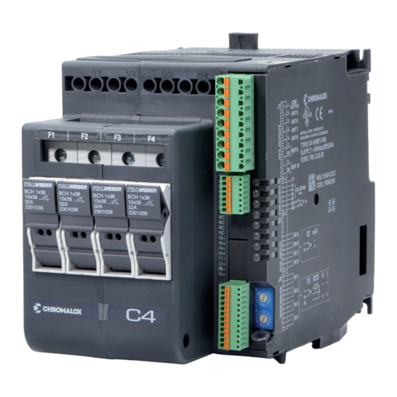
6. Controller Overview 6.1 Layout Front DIN rail mount for the C4-OP programming module. This mount is only present on models without fuse holders. 2. Screwdriver access to power connection screws. 3. Power supply connection terminals 4. Heat sink ventilation screen: DO NOT OBSTRUCT 5. -
Page 10: Cooling Fan
6.2 Cooling Fan PERIODIC CLEANING Every 6-12 months (depending on the dust level of the installation) blow a compressed air jet downward through the upper rectangular cooling grilles (on the side opposite the fan). This will clean the internal heat dissipater and the cooling fan. -
Page 11: Connections And Indication
7. Connections and Indication 7.1 Power Connections Model without fuse holder Model with fuse holder F1,F2,F3,F4/ 7.2 Power Wiring Considerations Model 30kW 60kW 80kW Max Current 16 Amps 30 Amps 40 Amps 0.2 - 6mm 24 - 10 AWG 0.2 - 6mm 24 - 10 AWG 0.5 - 16mm 20 - 6 AWG... -
Page 12: Input & Output Connections
7.3 Input & Output Connections • Use adequately compensated cable for thermocou- • For 2-wire RTDs, make the connection indicated in- ple inputs. Maintain polarity by avoiding junctions stead of the third wire. on the cables. • Refer to the applicable Connectors Detail starting in •... -
Page 13: Rotary Switches
7.5 Rotary Switches Switch Drescription Defines Address of Controller Module Available address: 00...99 7.6 Connector Detail 7.6.1 Connector J1 / J1a (Note: If Auxiliary Outputs O5 - O8, are present, connector J1a becomes J1.) 0.2 - 2.5mm 24-14 AWG 0.25 - 2.5mm 23-14 AWG Outputs 5 - 8: Logic or Analog Output Type Logic outputs: 18 - 36Vdc, max 20mA... - Page 14 When the optional Auxiliary Output type “A” (Analog) is selected, one must choose whether the output is Voltage- based (default) or Current-based. This selection is carried out via proper jumper placement on the board as follows: Output Card Output Card Output Card...
- Page 15 Outputs 5 - 8: TRIAC Type TRIAC outputs: Voltage: 24...230Vac, max 1A Wiring Schematic for Outputs 5 - 8, TRIAC Outputs PIN Legend Name Description Com O5-O8 Com O5-O8 Com O5-O8 Outputs Common Output 5 Output 6 Output 7 Output 8 Outputs 5 - 8: Relay Type Outputs Out 5 - Out 8, Relay outputs: Ir = 3A max, NO (normally open) V = 250V/30 Vdc cosw = 1;...
-
Page 16: Connector J2
Outputs 9, 10: Relay Type Outputs Out 9, Out 10, Relay outputs: 5A max V = 250V/30Vdc cosw = 1; I = 5A max Wiring Schematic for Outputs 9 & 10, Relay Outputs PIN Legend Name Description Com O9 Output Common O9 Output O9 Com O10 Output Common O10... -
Page 17: Connector J3
7.6.3 Connector J3 (Auxiliary Inputs) 0.14 - 0.5mm 28-20 AWG 0.25 - 0.5mm 23-20 AWG Wiring Schematic for J3 - Auxiliary Inputs PIN Legend Name Description No Connection No Connection No Connection No Connection Auxiliary Input 5 Auxiliary Input 5 Auxiliary Input 6 Auxiliary Input 6 Auxiliary Input 7... -
Page 18: Connector J4
7.6.4 Connector J4 (Inputs 1 - 4) 0.14 - 0.5mm 28-20 AWG 0.25 - 0.5mm 23-20 AWG Inputs 1 - 4 PIN Legend 60mV/Tc 1V/20mA Pt100 Linear Input Linear Input Input IN1+ IN2+ II3- IN3+ IN4+... -
Page 19: Dip-Switch Configuration
7.7 Dip-Switch Configuration Dip Switch Legend Function Description Switch Load Connection See Load Configuration Table Below. No Function Frequency ON: 60 Hz OFF: 50 Hz Factory Default ON: Resets Controller to Factory Settings Simulation ON: Simulation Mode RS485 ON: When the device is the ONLY RS-485 Communications device or when it is the LAST RS-485 device Load Configuration Table... -
Page 20: Serial Communication Ports
7.8.1 Port1 (Standard Local Bus): Connectors S1, S2, S3 Modbus RTU/RS485 Serial Interface 1 9 2 F 1 9 0 F Connector S3 accepts the C4-OP local interface terminal. See the C4-OP Section for more detail. Connector S1/S2 RJ10 4-4 Pin... -
Page 21: Port2 (Optional Fieldbus)
7.8.2 Port2 (Optional Fieldbus): Connectors S4, S5 A. Modbus RTU/RS485, Modbus RTU/RS485 S5 Female RJ10 Connector S4 Female RJ10 Connector End of line Modbus Termination Dip Switch* Connector S4/S5 RJ10 4-4 Pin Name Description Note (*) Enable Fieldbus DIP Switch GND1 (**) on last device on Modbus RS485 line... - Page 22 B. Modbus RTU/RS485, Profibus DP Interface S5 Female DB9 Connector S4 Female RJ10 Connector Yellow LED Red LED Green LED Connector S4 RJ10 4-4 Pin Name Description Note (**) Connect the GND signal to GND1 (**) Modbus devices with a line distance >...
- Page 23 C. Modbus RTU/RS485, CANopen Interface S5 Male DB9 Connector S4 Female RJ10 Connector Red LED Green LED Connector S4 RJ10 4-4 Pin Name Description Note (**) Connect the GND signal GND1 (**) among Modbus devices with a line distance > 300 ft. (100 m) Rx/Tx+ Data reception/transmission (A+) Rx/Tx-...
- Page 24 D. Modbus RTU/RS485, DeviceNet Interface S5 Male Connector S4 Female RJ10 Connector Red LED Green LED Connector S4 RJ10 4-4 Pin Name Description Note (**) Connect the GND signal to GND1 (**) Modbus devices with a line distance > 300 ft. (100 m) Rx/Tx+ Data reception/transmission (A+) Rx/Tx-...
- Page 25 E. Modbus RTU/RS485, Modbus TCP/Ethernet Interface S5 Female RJ45 Connector S4 Female RJ10 Connector Yellow LED Green LED Connector S4 RJ10 4-4 Pin Name Description Note (**) Connect the GND signal GND1 (**) among Modbus devices with a line distance > 300 ft. (100 m) Rx/Tx+ Data reception/transmission (A+) Rx/Tx-...
- Page 26 Modbus RTU/RS485, Ethernet IP Interface or Modbus RTU/RS485, EtherCAT Interface or Modbus RTU/RS485, ProfiNET Interface LED Logic - Ethernet IP Fieldbus Module H1 LED GREEN Module State H2 LED RED Module State H7 LED RED Network State H8 LED GREEN Network State LED Bicolor GREEN (H1) RED (H2)
-
Page 27: Connection Example: Communication Port
A. Supervisory PC/PLC with multiple C4 Modules, with C4-OP. May need to use Autobaud to synchronize communications. B. HMI Connection via Modbus RTU (RS-485) to four C4 Modules May need to use Autobaud function to synchronize communications. C. SCADA System with fieldbus interface, Single Master Setup... - Page 28 D. C4 with Multiple Master Communications Ports This configuration will allow two masters to simultaneously operate. This will allow the fieldbus to operate, while allowing the 2nd port to be used for local information, verification of process, or for configuration tool C-PWR software to be utilized.
- Page 29 E. C4 with a Single Master Communication Port Use Autonode Sequence for configuration. See section 12.2 C4 or C4-IR Fieldbus Network Purple: Fieldbus Network wiring to Master Unit. SW7 must be set to “off” on all units. Blue: Fieldbus Network Slave Unit connection via RS-485.
- Page 30 F. Multiple Fieldbus Connections C4 or C4-IR Fieldbus Network Purple: Fieldbus Network wiring to Master Unit. SW7 must be set to “off” on all units.
-
Page 31: Load Connection Examples
3Ø Delta 3Ø Wye (Star) ÷ R ÷ R The model C4 has specific dipswitch settings for the various load configurations. Incorrect- ly setting with a mismatch load configuration could result in unpredicted results. Please re- fer to section 7.7 or the Load Connection ex-... - Page 32 Open Delta & Wye Three phase heating circuits are most efficient when operated under balanced conditions. If it is necessary to oper- ate an unbalanced load, the equations below can be used to calculate the circuit values for open three phase Delta or Wye circuits.
-
Page 33: Single-Phase Loads, 3-Phase Line With Neutral
8.1 4 Single-Phase Loads, 3-phase line with neutral Dip Switch Load Connection Type The model C4 has specific dipswitch settings 4 independent zones for the various load configurations. Incorrectly OFF OFF OFF (4 single phase loads) setting with a mismatched load configuration could result in unpredicted results. -
Page 34: Two 3-Phase Loads, Closed Delta
8.3 Two 3-Phase Loads, Closed Delta F3 U3 F4/N U4 Dip Switch Load Connection Type Zone 1 & 3: Two 3-phase loads, OFF OFF closed delta connection 8.4 Two 3-phase loads, star (wye) without neutral LOAD 2 F3 U3 F4/N U4 Dip Switch Load Connection Type Zone 1 &... -
Page 35: One 3-Phase Load Active, One 3-Phase Load Inactive, Wye Without Neutral
8.5 One 3-phase load active, One 3-phase load inactive, Wye without neutral Dip Switch Load Connection Type Zone 1: 3-phase load, star (wye) connection, with neutral 8.6 One 3-phase load, inside delta F1 U2 F2 U3 F3 U4 Dip Switch Load Connection Type Zone 1: 3-phase load, open delta connection... -
Page 36: Inductive And Transformer Coupled Load Guidelines
9. Inductive and Transformer Coupled Load Guidelines The model C4 should not be used for Inductive or Transformer Coupled Loads. The model C4-IR is capable of be- ing used for these types of loads. Please refer to the C4-IR Hardware Manual for more details. -
Page 37: Autobaud Function
1. Connect the serial cables for all modules on the net- work to serial 1 and to the supervision terminal. 2. Set the rotary switch on the C4 modules to be in- stalled, or on all modules present in case of first in- stallation, to position “0+0”. -
Page 38: Specifications
12. Specifications INPUTS IN1 Analog Process Inputs Function Acquisition of process variable Max. Error 0,2% f.s. ± 1 scale point at room temperature of 25°C Thermal drift < 100 ppm/˚C f.s. Sampling time 120 ms J,K,R,S,T Thermocouple Tc (ITS90) (IEC 584-1 ,CEI EN 60584-1, 60584-2) Fault cold junction comp 0,1˚/˚C Pt1 00 (DIN 43760) Resistance thermometer RTD (ITS90) - Page 39 OUT9, ... , OUT10 Alarms Function Configurable (default: alarms) Relay Type 5A NO Contact, 250V/30Vdc COSw =1 COMMUNICATIONS PORT 1 (present) Function Local serial communication Protocol ModBus RTU Baudrate Settable to 1,2...57.6kbits/s, (default 19.2 kbit/s) Address Node Settable by rotary switch RS485 Type 1500V isolation, double connector RJ10 telephone type 4-4...
- Page 40 Alarm is assigned to an output, configurable as: maximum, minimum, sym- Configurable Alarms metrical, absolute/deviation, LBA, HB Alarm Masking Exclusion at power-up, latch, reset by digital input SCR in short circuit (presence of current with control OFF) Diagnostics SCR open (presence of voltage on SCR with control ON) Load interrupted or no voltage (no current, no voltage on SCR with control ON) Connection and Load Types 4 loads single-phase,...
- Page 41 VOLTAGE/CURRENT CONSIDERATIONS Current (Amp) Voltage (VAC) Power (kW) Max. Per Channel Range Nominal Working Per Channel Controller Total 13.3 15.4 (4x16A) 17.7 25.6 30.7 14.4 25.0 28.8 24 - 530 (4x30A) 33.2 12.0 48.0 14.4 57.6 19.2 33.3 38.4 (4x40A) 11.1 44.3 16.0...
-
Page 42: Ordering Information
13. Ordering Information Model C4 SCR Power Controller Code Current Per Loop @ 40˚C (104˚F) Ambient, continuous service (110 Vac to 480 Vac) (See note 3) 164 16 Amps/Loop 304 30 Amps/Loop 404 40 Amps/Loop Code Auxiliary Outputs None Relay... -
Page 43: Configuration And Programming
14.1 C-PWR Configuration Software Program See C-PWR Configuration Software Program instruction manual for proper program installation. 14.2 C4/C4X/C4-IR Programming Manual See C4/C4X/C4-IR Programming Manual for complete controller set-up of communications, inputs, outputs, alarms and control modes. 15. Accessories 15.1 Fuses and Fuse Holders... - Page 44 15.3 Configuration Software and Cabling Configuration kit for C4 product line by means of PC with USB (Windows environment). Software is compatible with all C4 models. Download free at www.Chromalox.com - Allows you to read and write all of the parameters of a single C4 device...
Need help?
Do you have a question about the C4 and is the answer not in the manual?
Questions and answers