Advertisement
Table of Contents
- 1 Table of Contents
- 2 Getting Started
- 3 Installation
- 4 Temperature Control Operation
- 5 System Operation
- 6 Diagnostics
- 7 Maintenance
- 8 Troubleshooting
- 9 Specifi Cations
- 10 CMX Warranty and Limitation of Remedy and Liability
- 11 Index
- 12 Appendix Acmx-180 Model for Low Pressure Applications
- 13 Appendix Bcmx Closed Loop to Open Loop Cooling Conversion
- 14 Appendix CCMX Open Loop to Closed Loop Cooling Conversion
- Download this manual
System Model Number and Rating ___________________________________________________
Part Number _______________________________________
Customer _______________________________________________________________________
Customer Order Number _____________________________ Date _______________________
Issue Date
January 2012
Part Number: 161-123417-023
User Instructions
TM
Serial Number _______________
User's Manual
Sales PQ445-5
TM
Advertisement
Table of Contents

Related Manuals for Chromalox MICROTHERM CMX Series


Summary of Contents for Chromalox MICROTHERM CMX Series
- Page 1 System Model Number and Rating ___________________________________________________ Part Number _______________________________________ Serial Number _______________ Customer _______________________________________________________________________ Customer Order Number _____________________________ Date _______________________ User’s Manual Part Number: 161-123417-023 Issue Date User Instructions Sales PQ445-5 January 2012...
- Page 2 User Instructions...
-
Page 3: Table Of Contents
Table of Contents _____________________________________________ Section Topic Page Getting Started ..................... 1 Installation ....................5 Temperature Control Operation ..............13 System Operation ..................19 Diagnostics ....................21 Maintenance....................23 Troubleshooting .................... 31 Specifi cations ....................33 CMX Warranty and Limitation of Remedy and Liability......37 Index ...................... - Page 4 Illustrations ___________________________________________________ Figure Topic Page System Photo ....................2 Control Panel ....................3 Open-Loop System Piping ................6 Open-Loop Piping Connections ..............7 Closed-Loop System Piping ................9 Closed-Loop Piping Connections ..............10 Power Connection Terminals................. 11 Control Panel Layout ..................13 Controller Displays and Pushbuttons .............
-
Page 5: Getting Started
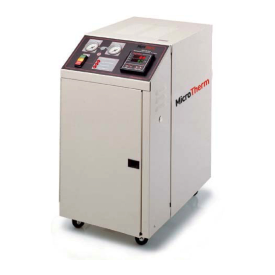
Read and understand all instructions in this user’s manual and the enclosed 2104 temperature control instruction manual before attempting to install or operate system. Congratulations on purchasing the Chromalox CMX Series mi- croTHERM™ Temperature Control System. This system has Introduction been thoroughly engineered, carefully built, and fully tested to assure years of service. - Page 6 Figure 1.1 System Photo Operating temperatures of ® ® ASME pressure relief valve Incoloy sheath Chromalox 50° to 250°F for a wide opens if system pressure heating elements. variety of applications exceeds 125 psi, ensuring safe operation Integral solenoid valve for precise temperature control and optimum fl...
- Page 7 Figure 1.2 Control Panel Dual pressure gauges for monitoring of both to process and from process pressures. Pump Diagnostic Indicators Chromalox’s 2104 Temperature START/STOP and Process Controller Pushbuttons User Instructions...
- Page 8 Ordering Information Model Volts Total Amperage Open-Loop Cooling CMX-250-4 13.6 CMX-250-4 CMX-250-9 24.5 CMX-250-9 12.2 CMX-250-12 31.7 CMX-250-12 15.8 CMX-250-18 46.1 CMX-250-18 23.1 CMX-250-24 60.5 CMX-250-24 30.3 Closed-Loop Cooling CMX-250-4C 13.6 CMX-250-4C CMX-250-9C 24.5 CMX-250-9C 12.2 CMX-250-12C 31.7 CMX-250-12C 15.8 CMX-250-18C 46.1 CMX-250-18C...
-
Page 9: Installation
Section 2 Installation ___________________________________________________ Hydraulic Installation Open-Loop Cooling Section Contents Hydraulic Installation Closed-Loop Cooling Electrical Installation Before proceeding with the installation of the open-loop system, Before please take note of the following important information: Open-Loop Hydraulic Installation 1. Reduced diameter fi ttings may be used if they do not reduce fl... - Page 10 1. Locate the unit as close as possible to the controlled process Hydraulic Installation in order to minimize pressure drops. Make sure the unit is Open-Loop sitting on a solid, level foundation. 2. Using 1 ” NPT or larger schedule 40 pipe (fl exible hose suitable for 150 psi and 250°F minimum service conditions can be used), connect the 1 ”...
- Page 11 Figure 2.2 Open-Loop Cooling Piping Connections ® Chromalox " DRAIN/ COOLING OUTLET 6" FROM PROCESS TO PROCESS " " WATER SUPPLY/ COOLING INLET 6" 7" 4" 15" Rear View Note: Dimensions are nominal ± ” User Instructions...
- Page 12 Before proceeding with the installation of the Closed-loop Before system, please take note of the following information: Closed-Loop Hydraulic Installation 1. Reduced diameter fi ttings may be used if they do not reduce fl ow rate and increase pressure drop signifi cantly. Galvanized steel unions are recommended at all connections.
- Page 13 4. Connect the cooling water supply (30 psi to 80 psi) to the Hydraulic Installation unit’s ” NPT “WATER SUPPLY/COOLING INLET” port Closed-Loop with suitable pipe or hose. (continued) 5. Connect the ” NPT port identifi ed as “COOLING OUTLET” to a cooling water return line or plant drain that contains no valves or obstructions that could impede discharge.
- Page 14 Figure 2.4 Closed-Loop Piping Connections ® Chromalox COOLING OUTLET " WATER SUPPLY/ COOLING INLET 6" FROM PROCESS TO PROCESS " " 6" 4" 7" 15" Rear View Note: Dimensions are nominal ± ” User Instructions...
- Page 15 Electrical WARNING Installation 1. Hazard of electric shock. The heat transfer system must be grounded using grounding means provided in control box and employing wiring by a qualifi ed electrician in accordance with National Electric Code. Failure to comply can result in electrical shock or electrocution. 2.
- Page 16 Pump Rotation Check 4. With power off, check the wiring connections by tugging on the lines. Tighten all terminals in the control area. These can loosen due to vibration in shipping. 5. Close the front electrical enclosure door. Pull the top cover off of the heat transfer system and locate the top of the pump motor.
-
Page 17: Temperature Control Operation
Section 3 Temperature Control Operations ______________________________ Control Panel Temperature Controller Operation Figure 3.1 Inlet Pressure Outlet Pressure “From Process” “To Process” Control Panel Layout START/STOP Pushbuttons Diagnostic Indicators Temperature Controller System shuts down if any diagnostic Top Display reads current system outlet START Press to start the pump. - Page 18 The Chromalox 2104 1/4 DIN temperature controller is a high- Temperature performance, single-loop controller used in the CMX system. Controller The 2104 controller has two control outputs for heating and Operation cooling that can be confi gured separately and provide fl exible temperature control for the CMX.
- Page 19 All control parameters, selections and calibration procedures for PAGE/MENU the temperature controller are accomplished through simple Setup MENU selections. These MENU selections are organized into PAGES. The Display PAGE (DISP) allows you to view the status of the controller. The Control Page (CTRL) allows you to change the control setpoint and security lock.
- Page 20 To change a MENU value: ▲ ▼ After the MENU is selected and displayed, use the pushbuttons to change the value. For large adjustments (for example, 100 to 200), hold the pushbutton pressed and the display will change more quickly. RESET RESET To return to Operating Mode:...
- Page 21 To access and enter the Security Code: 1. Press and hold for more than 3 seconds to enter Setup RESET Mode. Security Lock is the fi rst menu that will appear (LOCH). ▲ ▼ 2. To change the Security Code, press until the correct security code is displayed (458 to change controller setup).
- Page 22 Notes User Instructions...
-
Page 23: System Operation
Section 4 System Operation _____________________________________________ WARNING On both open Closed-loop systems, turn on water and insure the water supply lines are free of obstructions BEFORE energizing the heater. Such obstructions could prevent the thermal expansion of water from backing up into this line, thereby increasing system pressure until the relief valve opens. - Page 24 5. Assure that Pump Rotation Check was performed per instructions on page 12. 6. Start the pump by pressing on the front panel. The START pump indicator light will illuminate. 7. Once temperature has stabilized at the setpoint level, review controllability of the system. If the temperature (displayed in the top display of the temperature controller) is fl...
-
Page 25: Diagnostics
Section 5 Diagnostics ___________________________________________________ Lower Water Pressure Section Contents Pump Overload Over Temperature Figure 5.1 Diagnostic Indicators All diagnostic functions will shut down the system and require Diagnostic Functions the operator to remedy the problem before it can be restarted. Low Water The pump, heater, and cooling will not operate while the pressure is low. - Page 26 The Pump Overload Indicator will illuminate when the pump Pump Overload draws too much current. Low line voltage, single phase power Indicator input, and a seized pump motor are all possible causes for pump overload. WARNING Disconnect system power, if the Pump Overload Indicator is illuminated.
-
Page 27: Maintenance
Section 6 Maintenance ________________________________________________ Section Contents Shut Down Heater Removal/Replacement Pump Removal/Replacement Heat Exchanger Removal/Replacement (closed loop systems) WARNING Disconnect all power before servicing or performing maintenance to the system. Do not attempt to service system while it is operating. Failure to comply can result in: a. - Page 28 Drain the unit before taking it out of service for a period of Draining time, or if it is exposed to freezing temperatures while out of service. 1. To drain the unit completely, move it to an inclined position with the front of the system raised. 2.
- Page 29 Heater WARNING Removal/ Hazard of electric shock or electrocution. Disconnect all power Replacement and piping to system. 1. Disconnect all power to the system. 2. Bleed pressure and drain all water from the system. 3. Remove top panel. 4. Remove red top cover on the heater (see Figure 6.2, Heater/Chamber Photo).
- Page 30 WARNING Hazard of electric shock or electrocution. Disconnect all power and piping to system. 1. Disconnect all power to the system. Pump Removal/Replacement 2. Bleed pressure and drain all water from the system. 3. Remove top and side panels. 4. Remove pump motor wiring cover panel (2 screws). 5.
- Page 31 1. Disconnect all power to the system. Heat Exchanger Removal/Replacement 2. Bleed pressure and drain all water from the system. (Closed loop system) 3. Remove top panel. 4. Remove cover on the cooling solenoid (see Figure 6.4, Heat Exchanger). 5. Disconnect “COOLING INLET” and “COOLING OUTLET”...
- Page 32 Figure 6.5 microTHERM™ Open and Closed-Loop Electrical Schematic Heater Customer Supplied 1M-1 4.5 KW to 24 KW Voltage 2L1 2T1 Pump Motor Pump Pump Overload Contactor Optional 120V Door Interlock DI-1 Fuse Pressure Pressure Switch Pressure Indication Pump Pump Start Stop Motor Control...
- Page 33 ........... Motor Thermal Overload 480V ......359-122078-095 ........... Transformer 240/480V ..........315-303786-001 ........... Caster (4 total) ............375-123425-003 ........... Control Voltage Fuse ..........128-123445-005 ........... Heater Contactor ...........See table above * These parts may vary for non-catalog items. Please consult your local Chromalox representative. (800-443-2640 or www.chromalox.com) User Instructions...
- Page 34 Figure 6.6 Replacement Parts From Process To Process Identifi cation CMX Series Temperature Control System Chromalox ® HEAT Pump COOL System Diagnostics OUT3 START Low Water Pressure OUT4 2104 Pump Overload RESET STOP PAGE PAGE Over Temperature Chromalox ® CONNECT...
-
Page 35: Troubleshooting
Section 7 Troubleshooting ______________________________________________ Troubleshooting Guide—For qualifi ed personnel only Symptom Probable Cause Correction Unit will not start, control 1. Unit not wired correctly. 1. Check wiring. display does not light. 2. Disconnect switch OFF. 2. Turn disconnect ON. 3. Blown fuse. 3. - Page 36 Refer to 2104 Controller Technical manual, page 35, for further information. If you continue to have problems with the system after review of the above issues, please contact Chromalox Product Service at 866-736-6686 from 9 A.M. to 5 P.M. EST. User Instructions...
-
Page 37: Specifi Cations
Section 8 Specifi cations _______________________________________________ Standard 3/4 HP Pump Pump Nominal Heating Standard Process Drain/supply Approximate Size Flow Capacity Voltages Connections Dimensions (HP) (gpm) (kW) (inches dia.) (inches dia.) (inches) 240 or 480 240 or 480 29 height 240 or 480 1 1/4 NPT 1/4 NPT 25 depth... - Page 38 • Alternate Voltages: 208, 380, 575 VAC, 3 phase Other Options • Expanded Open Loop Cooling: increased cooling water fl ow • Expanded Closed Loop Cooling: 6.3 sq. ft. heat exchanger • Solid State Power Control: SCR heater switching • Surge Reduction valve: reduces water pressure spikes •...
- Page 39 User Instructions...
- Page 40 Notes User Instructions...
-
Page 41: Cmx Warranty And Limitation Of Remedy And Liability
LIMITATION Clause, it is specifi cally understood that Products and parts not manufactured and work not performed by Chromalox are warranted only to the extent and in the manner that the same are warranted to Chromalox by Chromalox’s vendors, and then only to the extent that Chromalox is... - Page 42 Upon Buyer’s submission of a claim as provided above and its Limitation of Remedy substantiation, Chromalox shall at its option either (i) repair or replace its Products, parts or work at the original f.o.b. point of delivery or (ii) refund an equitable portion of the purchase price.
-
Page 43: Index
Section 10 Index ________________________________________________________ Alarm Incoloy-sheathed heater 1, 2 • latching 17 Indicators • Overtemperature 13, 14, 17 • Diagnostic 3, 13, 19, 21 • Relay Action 17 • Low Pressure 3, 13, 19, 21, 28 • Overtemp 3, 13, 19, 21, 22, 28 Cabinet 2 •... - Page 44 Replacement Heating Elements and Contactors 29 Replacement Parts 29 Security Code 16 • Access 17 • Change 17 Security Lock 15 Setpoint 13, 14, 15, 19, 20 • Change 15 • Control 15 • Temperature 14, 19 Setup Mode 15 Shutdown 20, 21, 23 Solenoid Valve 2, 9, 28 Specifi...
- Page 45 Appendix A __________________________________________________ General Instruction All warnings and cautions denoted throughout this user’s manual also apply to the CMX-180 model. General instructions and specifi cations referring to the CMX-250 also apply to the CMX-180 with specifi c differences outlined below. Low Pressure Application The CMX-180 is designed to operate at pressures below 20 psi and temperatures up to 180°F.
-
Page 46: Appendix Acmx-180 Model For Low Pressure Applications
Appendix A microTHERM™: CMX-180 Open and Closed-loop Electrical Schematic Customer Heater 1L2 1T2 Supplied 9 KW 480 VAC 10.8 AMP 1L3 1T3 1M-1 2L1 2T1 Pump 3/4 H.P. Motor 1.7 FLA 80 VA 480 : 120 VAC (See Transformer Wire Diagram) 1PB-2 Pump Customer... -
Page 47: Appendix Bcmx Closed Loop To Open Loop Cooling Conversion
The basic operation involves removing the heat exchanger bundle and replacing it with a fl at plate. Please contact the Chromalox Customer Service department for more information and to order the necessary materials. -
Page 48: Appendix Ccmx Open Loop To Closed Loop Cooling Conversion
The basic operation involves removing the fl at plate and replacing it with a heat exchanger bundle. Please contact the Chromalox Customer Service department (1-800-368-2493) for more information and to order the necessary materials. - Page 49 DRAIN / COOLING OUTLET FROM Fig. 2 PROCESS PROCESS WATER SUPPLY COOLING INLET OPEN LOOP OPEN LOOP Figure 3: Open Loop Cooling COOLING OUTLET WATER SUPPLY COOLING INLET Fig. 1 FROM PROCESS PROCESS CLOSED LOOP CLOSED LOOP Figure 4: Closed Loop Cooling User Instructions...
- Page 50 Installation Steps 1. Drain fl uid from system and disconnect all power. 2. Fig. 2: Remove 1/4” NPT elbow (39), nipple (15) and nipple (40) from solenoid valve and keep solenoid valve for reinstallation. 3. Fig. 2: Remove fl ange (42). 4.
Need help?
Do you have a question about the MICROTHERM CMX Series and is the answer not in the manual?
Questions and answers