Table of Contents

Related Manuals for Chromalox 8040


Summarization of Contents
Installation
Unpacking
Procedure for removing the product from its packing and checking for damage.
Installation
Guidance on installing the instrument, including precautions and panel mounting.
Panel Cut-outs
Specifications and diagrams for instrument panel cut-out dimensions.
Panel-Mounting
Instructions and diagrams for securely mounting the instrument in a panel.
Plug-In Options
Options Modules and Functions
Overview of available plug-in modules for enhanced instrument functionality.
Auto Detection of Option Modules
Explanation of how the instrument automatically identifies installed option modules.
Preparing to Install or Remove Options Modules
Safety precautions and steps for safely removing and installing option modules.
Removing/Replacing Option Modules
Detailed procedure for removing and replacing option modules from the instrument.
Wiring Instructions
Options Modules and Functions
Guidelines for minimizing electrical noise effects during wiring.
Installation Considerations
General guidelines for safe and effective wiring installations in industrial environments.
Use of Shielded Cable
Recommendations for using shielded cable to prevent electrical noise induction.
Noise Suppression at Source
Methods for suppressing electrical noise directly at its source for better signal integrity.
Thermocouple Wire Identification Chart
Chart showing wire and sheath colors for common thermocouple types worldwide.
Connections and Wiring
Diagrams of rear terminal connections for 1/16, 1/4 & 1/8 DIN instruments.
Power Connections - Mains Powered Instruments
Instructions for connecting mains power to the instrument, including safety precautions.
Power Connections - 24/48V AC/DC Powered Instruments
Instructions for connecting low voltage AC/DC power to the instrument.
Universal Input Connections - Thermocouple (T/C)
Wiring details for connecting thermocouple inputs to the instrument.
Universal Input Connections – PT100 (RTD) input
Wiring details for connecting PT100 RTD inputs to the instrument.
Universal Input Connections - Linear Volt, mV or mA input
Wiring details for connecting linear DC voltage, millivolt or milliamp inputs.
Option Slot 1 – Relay Output Module
Wiring connections for a relay output module in Option Slot 1.
Option Slot 1 - SSR Driver Output Module
Wiring connections for an SSR driver output module in Option Slot 1.
Option Slot 1 - Triac Output Module
Wiring connections for a Triac output module in Option Slot 1.
Option Slot 1 – Linear Voltage or mADC Output module
Wiring connections for a linear voltage or mADC output module in Option Slot 1.
Option Slot 2 - Relay Output Module
Wiring connections for a relay output module in Option Slot 2.
Option Slot 2 - SSR Driver Output Module
Wiring connections for an SSR driver output module in Option Slot 2.
Option Slot 2 - Triac Output Module
Wiring connections for a Triac output module in Option Slot 2.
Option Slot 2 - Dual Relay Output Module
Wiring connections for a dual relay output module in Option Slot 2.
Option Slot 2 - Linear Voltage or mADC Output module
Wiring connections for a linear voltage or mADC output module in Option Slot 2.
Option Slot 3 - Relay Output Module
Wiring connections for a relay output module in Option Slot 3.
Option Slot 3 - SSR Driver Output Module
Wiring connections for an SSR driver output module in Option Slot 3.
Option Slot 3 - Linear Voltage or mADC Output module
Wiring connections for a linear voltage or mADC output module in Option Slot 3.
Option Slot 3 - Dual Relay Output Module
Wiring connections for a dual relay output module in Option Slot 3.
Option Slot 3 - Transmitter Power Supply Module
Wiring connections for a transmitter power supply module in Option Slot 3.
Option Slot A Connections - RS485 Serial Communications Module
Wiring connections for the RS485 serial communications module in Option Slot A.
Option Slot A Connections - Digital Input Module
Wiring connections for a digital input module in Option Slot A.
Option Slot A Connections – Basic Auxiliary Input Module
Wiring connections for a basic auxiliary input module in Option Slot A.
Option Slot B Connections – Digital Input 2 (Full Auxiliary Module)
Wiring connections for a secondary digital input in Option Slot B.
Option Slot B Connections – 1/4 DIN & 1/8 DIN Full Auxiliary Input Module
Wiring connections for the full auxiliary input module in Option Slot B.
Powering Up
ENSURE SAFE WIRING PRACTICES ARE FOLLOWED
Critical safety warning about ensuring proper wiring practices before applying power.
Powering Up Procedure
Step-by-step procedure for powering up the instrument for the first time or after changes.
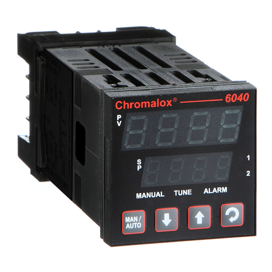
Overview of Front Panel
Description and illustration of the instrument's front panel layout and indicators.
Displays
Explanation of the dual line display and LED indicators for mode and status.
Keypad
Details on the instrument's keypad functions for navigation and adjustment.
LED Functions
Table detailing the meaning and behavior of the instrument's LED indicators.
Messages and Error Indications
Error/Faults conditions
Table listing error and fault conditions displayed on the instrument.
Instrument Operation Modes
Select Mode
Description of how to access different operation modes of the instrument.
Unlock Codes
Explanation of unlock codes required for accessing certain instrument modes.
Automatic Tune Mode
Details on using the automatic tune facility for controller tuning.
Product Information Mode
Read-only mode to check instrument hardware, firmware, and manufacturing info.
Navigating in the Product Information Mode
Instructions on how to navigate and view information within the Product Information Mode.
6040, 8040 & 4040 Controller – Model Group
6040, 8040 & 4040 Controllers - Configuration Mode
Mode for initial configuration or major changes to instrument characteristics.
Entry into the Configuration Mode
Procedure for accessing the Configuration Mode, including security lock code.
Scrolling through Parameters and Values
How to navigate through parameters and their values within a mode.
Changing Parameter Values
Procedure for selecting and modifying parameter values.
6040, 8040 & 4040 Controllers – Communications Parameters
Bit Parameters
List and description of bit parameters for Modbus communications.
Word Parameters
List and description of word parameters for Modbus communications.
6040, 8040 & 4040 – Setup Mode
Entry into the Setup Mode
Procedure for entering the Setup Mode after configuration is complete.
6040, 8040 & 4040 Controllers - Operator Mode
6040, 8040 & 4040 Controllers – Extended Operator Mode
Using PC software to extend Operator Mode displays with Setup Mode parameters.
Navigating in Operator Mode
How to move between displays and adjust values in Operator Mode.
Adjusting the Local Setpoint(s)
Procedure for adjusting local setpoints within the limits set in Setup Mode.
Adjusting the Setpoint Ramp Rate
How to adjust the setpoint ramp rate for controlled setpoint changes.
Manual Control Mode
How to select and use manual control mode for the instrument.
Selecting/deselecting Manual Control Mode
Using front panel keys to toggle between automatic and manual control modes.
6040, 8040 & 4040 VMD Controller – Model Group
Special Wiring Considerations for Valve Motor Control
Specific wiring advice for Valve Motor Drive controllers to prevent issues.
6040, 8040 & 4040 VMD Controllers - Configuration Mode
Entry into the Configuration Mode
Procedure for accessing the Configuration Mode for VMD controllers.
6040, 8040 & 4040 Valve Motor Drive – Setup Mode
Entry into the Setup Mode
Procedure for entering the Setup Mode for VMD controllers.
Scrolling through Parameters & Values
How to navigate parameters and values in VMD Setup Mode.
Changing Parameter Values
Procedure for selecting and modifying parameter values in VMD Setup Mode.
Adjusting the Valve Parameters
Steps to adjust valve parameters like open/closed positions and limits.
Set Valve Opened Position & Set Valve Closed Position
Procedure to set the instrument's input value for valve end stops.
Valve Position Clamping
Setting upper and lower valve position limits to prevent driving past physical limits.
6040, 8040 & 4040 Valve Motor Drive - Operator Mode
6040, 8040 & 4040 Valve Motor Drive – Extended Operator Mode
Using PC software to extend Operator Mode displays for VMD controllers.
Navigating in Operator Mode
How to move between displays and adjust values in VMD Operator Mode.
Adjusting the Local Setpoint(s)
Procedure for adjusting local setpoints within VMD controller limits.
Adjusting the Setpoint Ramp Rate
How to adjust the setpoint ramp rate for VMD controllers.
Manual Control Mode
How to select and use manual control mode for VMD controllers.
Selecting/deselecting Manual Control Mode
Using front panel keys to toggle VMD control modes.
6040, 8040 & 4040 VMD Controllers – Serial Communications Parameters
Bit Parameters
List and description of bit parameters for VMD Modbus communications.
Word Parameters
List and description of word parameters for VMD Modbus communications.
10 6040 HBA Controller – Model Group
6040 - Configuration Mode
Mode for initial configuration or major changes to HBA controller characteristics.
Entry into the Configuration Mode
Procedure for accessing the Configuration Mode for HBA controllers.
11 6050 & 4050 Limit Controller – Model Group
6050 & 4050 Limit Controllers - Configuration Mode
Mode for initial configuration or major changes to Limit Controller characteristics.
Entry into the Configuration Mode
Procedure for accessing the Configuration Mode for Limit Controllers.
6050 & 4050 Limit Controllers – Setup Mode
Entry into the Setup Mode
Procedure for entering Setup Mode for Limit Controllers.
6040 HBA Controller – Communications Parameters
Bit Parameters
List and description of bit parameters for HBA Modbus communications.
Word Parameters
List and description of word parameters for HBA Modbus communications.
Manually Tuning Controllers
Single Control Tuning (PID with Primary Output only)
Technique for tuning PID controllers using primary output for stable control.
Dual Control Tuning (PID with Primary and Secondary Outputs)
Tuning PID controllers with both primary and secondary outputs for optimized control.
Valve Control Tuning (PI with VMD or Linear Outputs)
Tuning PI controllers for modulating valves using VMD or linear outputs.
Modbus Serial Communications
Physical Layer
Configuration settings for the physical layer of Modbus communication.
Link Layer
Description of the Modbus link layer communication protocol between master and slave.
Device Addressing
How to assign and use device addresses for Modbus communication.
Supported Modbus Functions
List of Modbus function codes supported by the instruments.
ASCII Communications
Physical Layer
Configuration settings for the physical layer of ASCII communication.
Device Addressing
How to assign and use device addresses for ASCII communication.
Session Layer
Description of the ASCII protocol session layer communication.
Calibration Mode
CALIBRATION IS ONLY REQUIRED FOR INSTRUMENTS IN WHICH CALIBRATION ERRORS HAVE BEEN ENCOUNTERED.
Important warning stating calibration is only needed if errors are detected.
Equipment Required For Checking or Calibrating the Universal Input
List of required equipment for calibrating the universal input.
Calibration Check
Procedure for checking the instrument's calibration accuracy.
Recalibration Procedure
Step-by-step procedure for recalibrating the instrument's input phases.
Appendix 1 - Glossary
Active Setpoint
The setpoint value currently used by the controller for target operation.
Actual Setpoint
The current value of the setpoint, which may differ if ramping.
Alarm Hysteresis
Adjustable band around alarm points to prevent rapid state changes and chatter.
Alarm Operation
Description of different alarm types and their corresponding output actions.
Alarm Inhibit
Disables alarms at power-up or when controller setpoint changes until alarm is inactive.
Annunciator
Special alarm output linked to Limit Output, activates on Exceed condition.
Automatic Reset (Integral)
Parameter to compensate for process load variations by biasing proportional output.
Auto Pre-Tune Type
Determines if Auto Pre-Tune facility is activated on power up for controller tuning.
Auxiliary Input
Secondary linear input for Remote Setpoint or Valve Position Indication.
Band Alarm 1 Value
Defines a process variable band for Alarm 1; alarm active if outside this band.
Band Alarm 2 Value
Defines a process variable band for Alarm 2; alarm active if outside this band.
Bias (Manual Reset)
Manually biases proportional output to compensate for load variations and startup errors.
Bumpless Transfer
Prevents sudden output changes when switching between Auto and Manual control modes.
Boundless VMD Control
Refers to Open Loop VMD control for valves without position feedback.
Cascade Control
Control strategy for applications with two or more capacities requiring precise regulation.
Communications Write Enable
Enables/disables parameter value changes via RS485 communications link.
Control Type
Defines if a controller has one or two control outputs for direction control.
Controller
Instrument types controlling a Process Variable using PID or On-Off methods.
CPU
Refers to the instrument's central processing unit controlling functions.
Current Proportioning Control
Control implementation using linear current or voltage outputs for precise control.
Cycle Time
Time period for cycling output on/off in time proportioning control for PID output.
Deadband
Refers to Overlap/Deadband parameter.
Derivative
Refers to Rate parameter.
Deviation Alarm 1 Value Type
Sets alarm point based on deviation from setpoint for Alarm 1.
Deviation Alarm 2 Value
Sets alarm point based on deviation from setpoint for Alarm 2.
Differential (On-Off Hysteresis)
Switching differential to prevent relay chatter in On-Off control.
Display Strategy
Alters parameters displayed in normal operator mode for user interface customization.
Elapsed Time
Total accumulated time an alarm has been active since last reset.
Exceed Condition
State occurring when Process Variable exceeds Limit Setpoint, shutting down process.
Exceed Time
Total accumulated time a Limit Controller has been in Exceed Condition.
Heater Current Monitor
Diagnoses heater element faults by monitoring heater current.
Indicator
Instrument displaying Process Variable and activating alarms at preset PV values.
Input Filter Time Constant
Parameter to filter extraneous impulses on the process variable for stable readings.
Input Range
Overall process variable input range and type selected by InPt parameter.
Input Span
Measuring limits defined by Scale Range Upper and Lower Limits for scaling.
Integral
Refers to Automatic Reset parameter.
Latching Relay
Relay output requiring a reset signal to deactivate after becoming active.
LED
Light Emitting Diode used for indicator lights on displays and panels.
Limit Controller
Protective device shutting down processes at a preset Exceed Condition.
Limit Hysteresis
Adjustable band on safe side of Limit Setpoint to prevent relay chatter.
Limit Setpoint
Pre-set value at which an Exceed Condition occurs.
Lock Codes
Four-digit codes required to enter Configuration, Set-Up, and Auto Tuning modes.
Logical Combination of Alarms
Combining two alarms logically (AND/OR) to create specific alarm outputs.
Loop Alarm Enable
Enables or disables loop alarm, which detects control feedback loop faults.
Loop Alarm Time
Duration of limit condition before loop alarm activation for On-Off control.
mADC
Milliamp DC, used for DC milliamp input and output ranges.
Manual Mode
Mode allowing manual control of output power, overriding PID algorithm.
Manual Mode Enable
Determines if operator selection and de-selection of manual control is enabled.
Master & Slave
Describes controller applications where one instrument controls another's setpoint.
Minimum Motor On Time
Minimum drive effort needed to initiate valve movement, preventing inertial effects.
Modulating Valve
A valve positioned by an incorporated motor, often used for temperature control.
Motor Travel Time
Time taken for the valve to travel between its physical end stops, used for algorithm calculation.
Multi-Point Scaling Enable
Enables up to 9 breakpoints to linearize input signals for indicators.
Multi-Point Scaling Set Up
Configures input scale values and display values for indicator breakpoints.
Offset
Modifies measured process variable value to compensate for input errors.
On-Off Control
Control method turning output on/off based on setpoint crossing, causing some oscillation.
On-Off Differential (Hysteresis)
Refers to Differential parameter.
Open Loop VMD
PID control algorithm not requiring valve position feedback for process control.
Overlap/Deadband
Defines proportional band portions where outputs are active (Overlap) or inactive (Deadband).
PI Control
Proportional and Integral control for modulating valves, without derivative action.
PID Control
Proportional, Integral, and Derivative control for accurate process variable stabilization.
PLC
Programmable Logic Controller used in machine control, suited for sequential applications.
Pre-Tune
Facility to artificially disturb start-up for approximate PID value calculation.
Primary Output Power Limit
Parameter to limit the primary output power level, used for process protection.
Primary Proportional Band
Portion of input span where primary output power is proportional to process variable.
Process High Alarm 1 Value
Defines the process variable value above which Alarm 1 becomes active.
Process High Alarm 2 Value
Defines the process variable value above which Alarm 2 becomes active.
Process Low Alarm 1 Value
Defines the process variable value below which Alarm 1 becomes active.
Process Low Alarm 2 Value
Defines the process variable value below which Alarm 2 becomes active.
Process Variable (PV)
The primary input variable measured by the instrument, converted to electronic signal.
Process Variable Offset
Refers to Offset parameter.
Rate (Derivative)
Parameter defining how control action responds to process variable rate of change.
Remote Setpoint (RSP)
Adjusts controller setpoint using an external analog input signal.
Remote Auxiliary Input Range
Defines the type and range of the linear input signal for the Auxiliary Input.
Remote Setpoint Lower Limit
Minimum value for Remote Setpoint input, constraining adjustments.
Remote Setpoint Upper Limit
Maximum value for Remote Setpoint input, constraining adjustments.
Remote Setpoint Offset
Adjusts Remote Setpoint input value to compensate for errors.
Retransmit Output
Linear output signal proportional to PV or Setpoint for external devices.
Retransmit Output 1 Scale Maximum
Scales a linear output module for retransmission of PV or SP to its maximum value.
Retransmit Output 1 Scale Minimum
Scales a linear output module for retransmission of PV or SP to its minimum value.
Retransmit Output 2 Scale Maximum
Scales retransmit output 2 to its maximum value, similar to Scale Max 1.
Retransmit Output 2 Scale Minimum
Scales retransmit output 2 to its minimum value, similar to Scale Min 1.
Retransmit Output 3 Scale Maximum
Scales retransmit output 3 to its maximum value, similar to Scale Max 1.
Retransmit Output 3 Scale Minimum
Scales retransmit output 3 to its minimum value, similar to Scale Min 1.
Reset
Refers to Automatic Reset parameter.
Reverse Acting
Refers to Direct/Reverse Action of Control Output.
Scale Range Upper Limit
Scales process variable into engineering units for linear inputs, or reduces range for TC/RTD.
Scale Range Lower Limit
Scales process variable into engineering units for linear inputs, or reduces range for TC/RTD.
Secondary Proportional Band
Proportional band portion for secondary output, opposite action to primary.
Self-Tune
Continuously optimizes tuning by monitoring process error (deviation) for stable control.
Setpoint Ramping Enable
Enables or disables the viewing/adjustment of Setpoint Ramp Rate in Operator Mode.
Setpoint Ramp Rate
Rate at which the actual setpoint value moves towards the target value during changes.
Setpoint Select
Determines if local or remote setpoint is active, based on configuration or digital input.
Setpoint Select Enable
Enables or disables operator selection of setpoints if remote feature is used.
Soft Start
Provides a gentle start-up phase to a lower temperature before reaching working temperature.
Solid State Relay (SSR)
External device replacing mechanical relays for faster switching and superior control.
Solenoid Valve
Electromechanical device controlling gas or liquid flow with two states: open or closed.
Tare
Allows setting the current Process Variable input to zero for easy offset compensation.
Three Point Stepping Control
Refers to Valve Motor Control.
Time Proportioning Control
Control method cycling output on/off within a cycle time to achieve desired output ratio.
Tuning
Adjusting PID controller parameters manually or automatically for optimum control.
Triac
Solid state device replacing mechanical relays for AC power applications, offering faster switching.
Valve Close Limit
Parameter to clamp the upper valve position, preventing the controller from driving past it.
Valve Motor Drive Control
Controls modulating valves using Open Loop VMD PI algorithm for precise positioning.
Valve Position or Flow Indication
Displays valve position or flow as a percentage, possible if Auxiliary Input fitted.
Valve Open Limit
Parameter to clamp the lower valve position, preventing the controller from driving past it.
VMD
Refers to Valve Motor Control.
Appendix 2 - Specification
Universal Input
General specifications for the universal input capabilities of the instrument.
General Input Specifications
Details on input sampling rate, resolution, types, impedance, and protection.
Thermocouple Ranges Available
Table listing available thermocouple sensor types and their temperature ranges.
Thermocouple Performance
Specifications for thermocouple calibration, accuracy, stability, and influences.
Resistance Temperature Detector (RTD)
Details on RTD input specifications, including ranges and performance.
RTD Ranges Available
Table listing available RTD sensor types and their temperature ranges.
RTD Performance
Specifications for RTD calibration, accuracy, stability, and influences.
DC Linear
Specifications for DC linear inputs, including available ranges.
DC Linear Ranges Available
Table listing available DC linear input ranges (mA, V, mV).
DC Linear Performance
Specifications for DC linear input accuracy, stability, and influences.
Auxiliary Inputs
Specifications for auxiliary input modules, including sampling rate, resolution, types, and isolation.
Digital Inputs
Specifications for digital input types (Voltage-free or TTL-compatible), including operation modes.
Heater Current Input
Specifications for the heater current input, including accuracy and span.
Output Specifications
Overview of available output module types for different option slots.
Output Module Types
Details the types of output modules available for Option Slots 1, 2, and 3.
Specifications of Output Types
Detailed specifications for single relay, dual relay, SSR driver, and triac output types.
Linear DC
Detailed specifications for linear DC outputs, including resolution, ranges, and accuracy.
Transmitter Power Supply
Specifications for the transmitter power supply output used for external transmitters.
Control Specifications
Key control parameters and their ranges, including tuning, setpoint, and output settings.
Process Alarms
Details on the number and types of process alarms supported by controllers and indicators.
Digital Communications
Specifications for digital communication types, protocols, and physical layers.
Reference Conditions
Standard conditions under which instrument specifications are measured.
Operating Conditions
Environmental and operational conditions under which the instrument is designed to function.
Standards
List of conformance norms, EMC, and safety standards applicable to the instrument.
Physical Specifications
Dimensions
Physical dimensions of the instrument, including depth and bezel size.
Mounting
Information on the instrument's mounting method and panel cut-out sizes.
Terminals
Description of the type of terminals used for connections.
Weight
The maximum weight of the instrument.
Appendix 3 - Order Tables
Model 40 Series Temperature and Process Controller
Order table detailing part codes for 40 Series Temperature & Process Controllers.
Code Output 1
Coding for selecting the type of Output 1 module.
Code Output 2
Coding for selecting the type of Output 2 module.
Code Output 3
Coding for selecting the type of Output 3 module.
Code Feature Option A
Coding for selecting Feature Option A modules.
Code Feature Option B
Coding for selecting Feature Option B modules.
Code Power Supply
Coding for selecting the instrument's power supply.
Limited Warranty
Reference to Chromalox limited warranty applicable to this product.
Need help?
Do you have a question about the 8040 and is the answer not in the manual?
Questions and answers